Multifunctional cable laying device and application

A cable laying and multifunctional technology, applied in the field of multifunctional cable laying devices, can solve the problems of inconvenient guidance, achieve the effects of reducing the use of auxiliary devices, easy installation, and preventing air gaps

Pending Publication Date: 2020-06-12
昆明瑞建送变电工程有限公司
View PDF0 Cites 5 Cited by
  • Summary
  • Abstract
  • Description
  • Claims
  • Application Information

AI Technical Summary

Problems solved by technology

[0003] The purpose of the present invention is to provide a multifunctional cable laying device and its application to solve the problem of inconvenient guidance of cables laid at corners, and at the same time it has multiple functions

Method used


Image

  • Multifunctional cable laying device and application
  • Multifunctional cable laying device and application
  • Multifunctional cable laying device and application

Examples


Embodiment 1

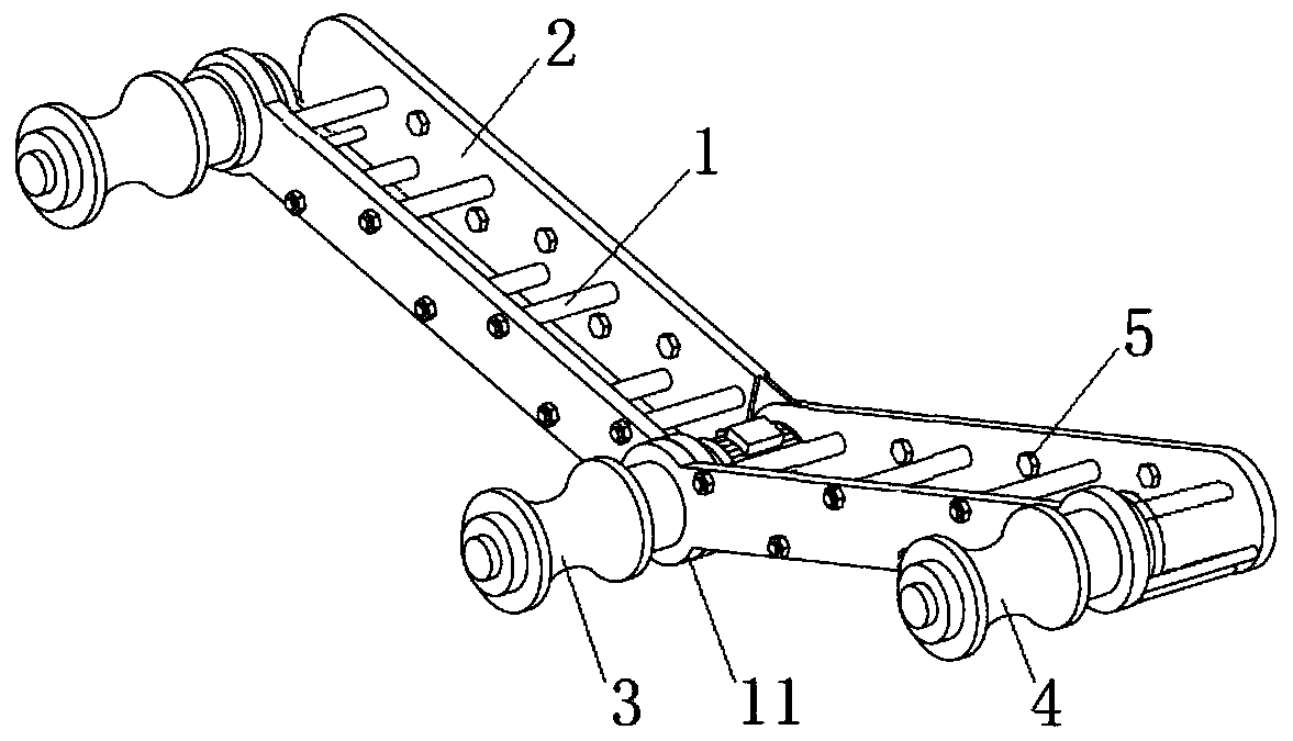
[0024] Such as figure 1As shown, a multifunctional cable laying device includes: a bracket 1 and a rotating shaft 11 installed on the bracket 1, two rotating arms 2 are installed with the rotating shaft 11 as the rotation center, and a driving roller 3 is installed at the position of the rotating shaft 11 and built-in The first servo motor, the axis of the driving wheel is parallel to the axis of the rotating shaft 11; the ends of the two rotating arms 2 are equipped with guide pulleys 4 whose axes are parallel to the driving roller 3; the rotating arms 2 are provided with several mounting holes 5. When laying cables at corner positions, firstly adjust the angle between the two rotating arms 2 of the multifunctional cable laying device provided in this embodiment. It is then installed at the corner position of the preset laying line through the mounting hole 5 on the rotating arm 2. During installation, fasteners such as expansion screws can be used to directly install on the ...

Embodiment 2

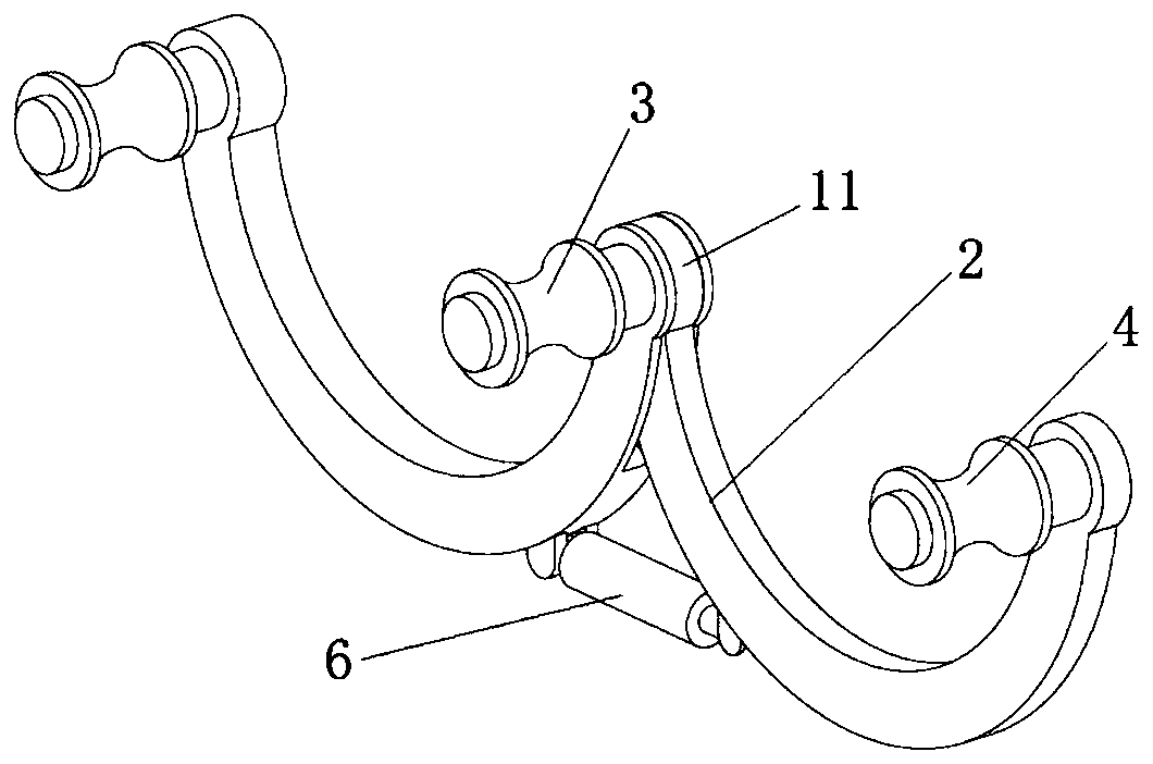
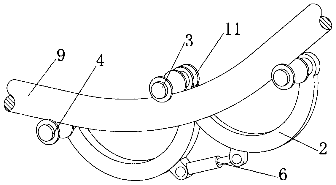
[0026] Such as image 3 As shown, a multi-functional cable laying device, the improvement on the basis of embodiment 1 includes: the second servo motor and the third servo motor are respectively installed on the two guide pulleys 4; the first, second and third servo motors The motors are all built-in motors, and their power is 400W. Each servo motor is also equipped with a control device of a PWM speed regulation module, and the control device is electrically connected with the first, second and third servo motors. The rotating arm 2 is curved, and an electric telescopic strut 6 is installed between the two swivel arms 2. The two ends of the electric telescopic strut 6 are installed on the two rotating arms 2 respectively, and the electric telescopic strut 6 realizes expansion and contraction through hydraulic pressure. , to adjust the angle between the two rotating arms 2 . The distance between the guide pulley 4 and the driving roller 3 on the two rotating arms 2 is 70cm. ...


PUM


Abstract

The invention discloses a multifunctional cable laying device and application, and relates to the technical field of cable laying equipment, the multifunctional cable laying device comprises a support, a rotating shaft installed on the support, two rotating arms installed with the rotating shaft as the rotating center, a driving roller with a built-in first servo motor installed at the position ofthe rotating shaft, wherein the axis of the driving roller is parallel to the axis of the rotating shaft; guide pulleys of which the axes are parallel to the driving roller are mounted at the tail ends of the two rotating arms; and a plurality of mounting holes are formed in the rotating arm.

Description

technical field [0001] The invention relates to the technical field of cable laying equipment, in particular to a multifunctional cable laying device and its application. Background technique [0002] The cable is usually a rope-like cable twisted by several or several groups of wires (at least two in each group). Each group of wires is insulated from each other and is often twisted around a center. Insulating covering. The cable is mainly composed of a conductive core, an insulating layer, a sealing sheath, and a protective covering layer. During the cable laying process, some right-angle corner obstacles will be encountered, and some larger-sized cables are not easy to bend and are easy to contact with corners and other places, causing damage to the cable insulation protection layer. At present, there is no special device to solve this problem, and the common method is to install pulleys at the corners for guidance. However, this method tends to generate uneven force on ...

Claims


Application Information

Patent Timeline
Patent Type & Authority Applications(China)
IPC IPC(8): H02G1/06B65H51/06B65H57/14
CPCB65H51/06B65H57/14B65H2701/34H02G1/06
Inventor 么洪坤
Owner 昆明瑞建送变电工程有限公司
Why Eureka
Try Eureka