
Performance state detection method and device for optical module in engineering application and electronic equipment

A state detection and engineering application technology, applied in the field of optoelectronic communication, can solve problems such as difficulty in optical module performance detection, and achieve the effect of ensuring monitorability

Active Publication Date: 2020-06-12
ZTE CORP
View PDF5 Cites 10 Cited by
  • Summary
  • Abstract
  • Description
  • Claims
  • Application Information

AI Technical Summary

Problems solved by technology

[0004] Embodiments of the present invention provide a method, device, and electronic device for detecting the performance status of optical modules in engineering applications, so as to solve the problem of difficult performance detection of optical modules in engineering applications

Method used


Image

  • Performance state detection method and device for optical module in engineering application and electronic equipment
  • Performance state detection method and device for optical module in engineering application and electronic equipment
  • Performance state detection method and device for optical module in engineering application and electronic equipment

Examples


Embodiment 1

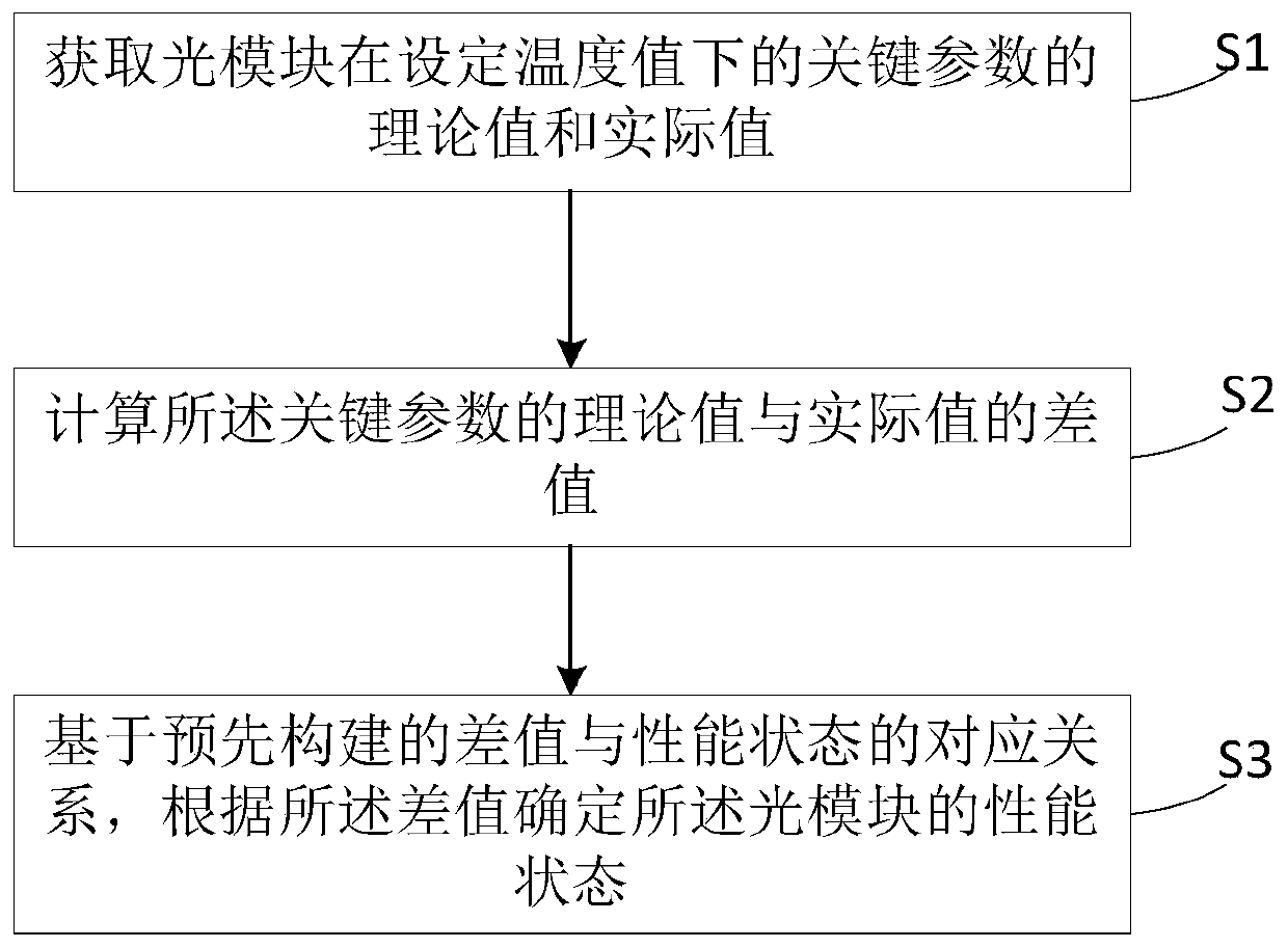
[0027] figure 1 A flow chart of a method for detecting the performance status of an optical module in an engineering application provided by an embodiment of the present application, as shown in figure 1 As shown, the method includes:

[0028] S1. Obtain the theoretical value and actual value of the key parameters of the optical module at the set temperature value;

[0029] Specifically, in the embodiment of the present application, the set temperature value is a temperature value set by itself according to specific circumstances, and may be any temperature value.

[0030] The theoretical value of the key parameter can be calculated according to a preset calculation formula, or can be obtained by searching a preset key parameter configuration table;

[0031] The actual value of the key parameter is the actual operating value of the optical module collected in real time in the engineering application.

[0032] S2. Calculate the difference between the theoretical value and th...


PUM


Abstract

The invention provides a performance state detection method and device for an optical module in engineering application and electronic equipment. The method comprises the steps: obtaining a theoretical value and an actual value of a key parameter of the optical module under a set temperature value; calculating the difference value between the theoretical value and the actual value of the key parameter, and automatically determining the performance health state of the optical module through the corresponding relation between the pre-constructed difference value of the key parameter and the performance health state of the optical module, thereby ensuring the performance monitoring performance of the optical module and the real-time updating and predictability of the performance health stateof the optical module.

Description

technical field [0001] Embodiments of the present invention relate to the technical field of optoelectronic communication, and in particular to a performance state detection method, device and electronic equipment of an optical module in engineering applications. Background technique [0002] An optical transceiver is a device composed of an optoelectronic device, a functional circuit, and an optical interface. The optoelectronic device includes two parts: transmitting and receiving. [0003] The optical module is a key device in the communication optical link. It converts the information at both ends of the system to photoelectric conversion. The sending end converts the electrical signal into an optical signal. After transmission through the optical fiber, the receiving end converts the optical signal into an electrical signal. key transit hub. However, in actual engineering applications, the hub is often a black box, which cannot detect the performance status of the opti...

Claims


Application Information

Patent Timeline
Patent Type & Authority Applications(China)
IPC IPC(8): H04B10/40H04B10/079
CPCH04B10/40H04B10/079H04B10/0795H04B10/07955H04B10/50G01M11/30
Inventor 张彪
Owner ZTE CORP
Learn More