
Rocking chair

The technology of a rocking chair and the other side is applied in the field of rocking chairs with automatic rocking function, which can solve the problems of reducing user experience, unfavorable promotion and application, and wear and tear of wooden floors, and achieves a sense of improvement, suitable for promotion and application, and comfortable to use. Effect

Inactive Publication Date: 2020-06-16
李清阳
View PDF1 Cites 0 Cited by
  • Summary
  • Abstract
  • Description
  • Claims
  • Application Information

AI Technical Summary

Problems solved by technology

The traditional rocking chair relies on the arc-shaped outriggers at the bottom to realize the front and rear swing. It does not have its own power source to realize the forward and backward swing. It needs to rely on manpower to realize its forward and backward swing, which reduces the user's sense of experience. In addition, When a traditional rocking chair rocks back and forth, its curved chair feet contact the ground alternately, which is easy to cause abrasion or noise to the ground, especially when it is placed on the bottom surface of the wooden floor at home, it is easy to damage wooden floor causing wear and tear
[0003] In order to solve the above existing problems, Chinese patent (application number: CN201710658257.X) discloses an electric rocking chair, although it can realize automatic rocking without manual intervention, but its structure includes the raw material storage container of the water hydrogen machine, the water hydrogen machine Including methanol water reforming hydrogen production device, liquid pump, hydrogen fuel cell, air pump and other devices, its structure is complex, and it is not popularized and applied. In addition, the curved base at the bottom can swing back and forth, which has the above-mentioned problems that are easy to cause wear on the ground.

Method used


Image

  • Rocking chair
  • Rocking chair
  • Rocking chair

Examples


Embodiment Construction

[0034] The following are specific embodiments of the present invention and in conjunction with the accompanying drawings, further describe the technical solution of the present invention, but the present invention is not limited to these embodiments.

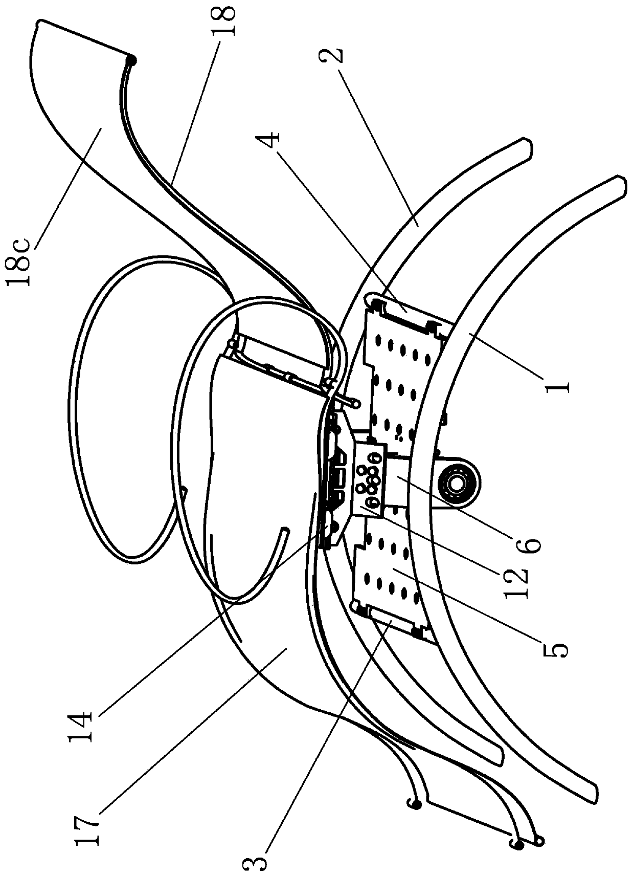
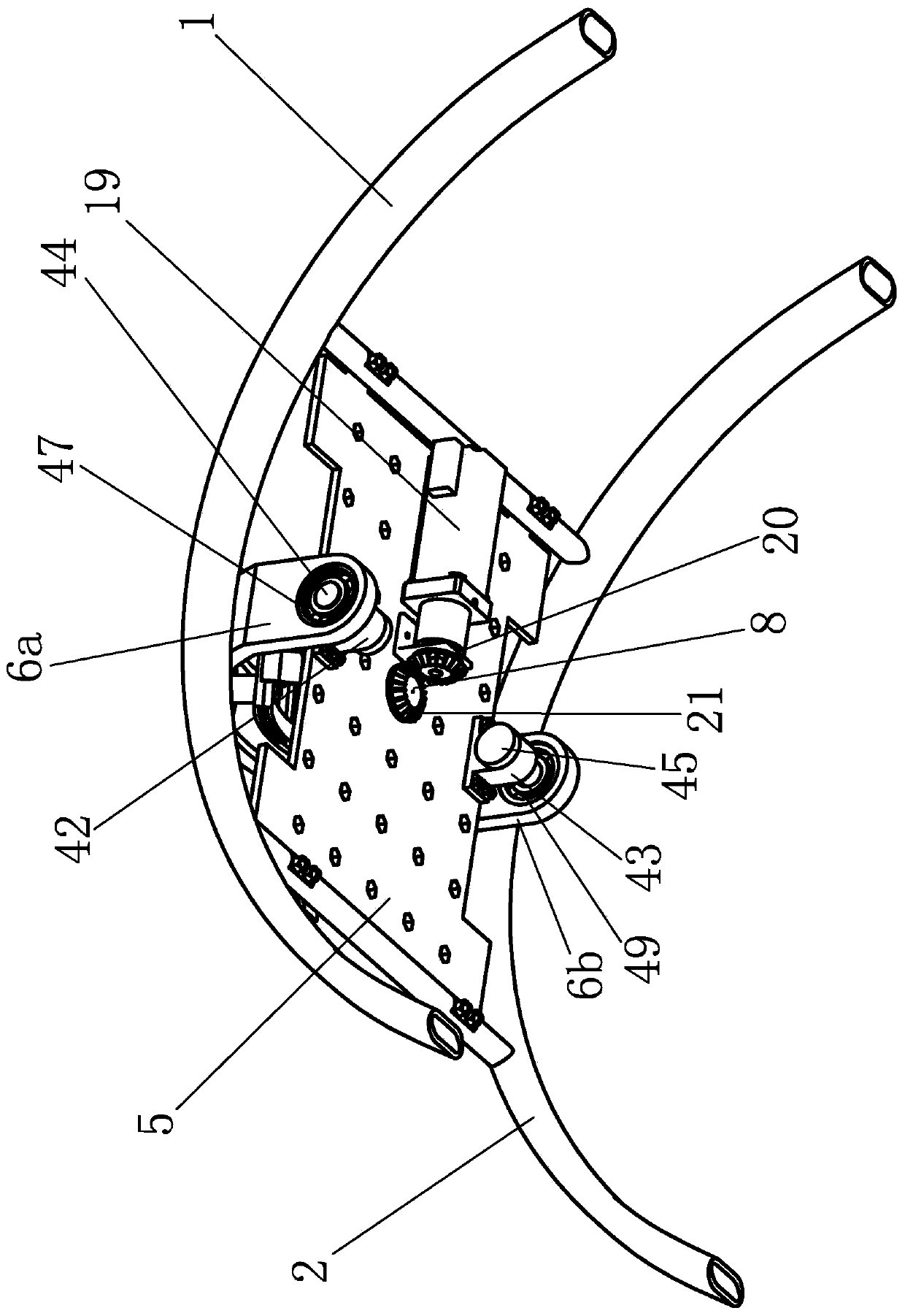
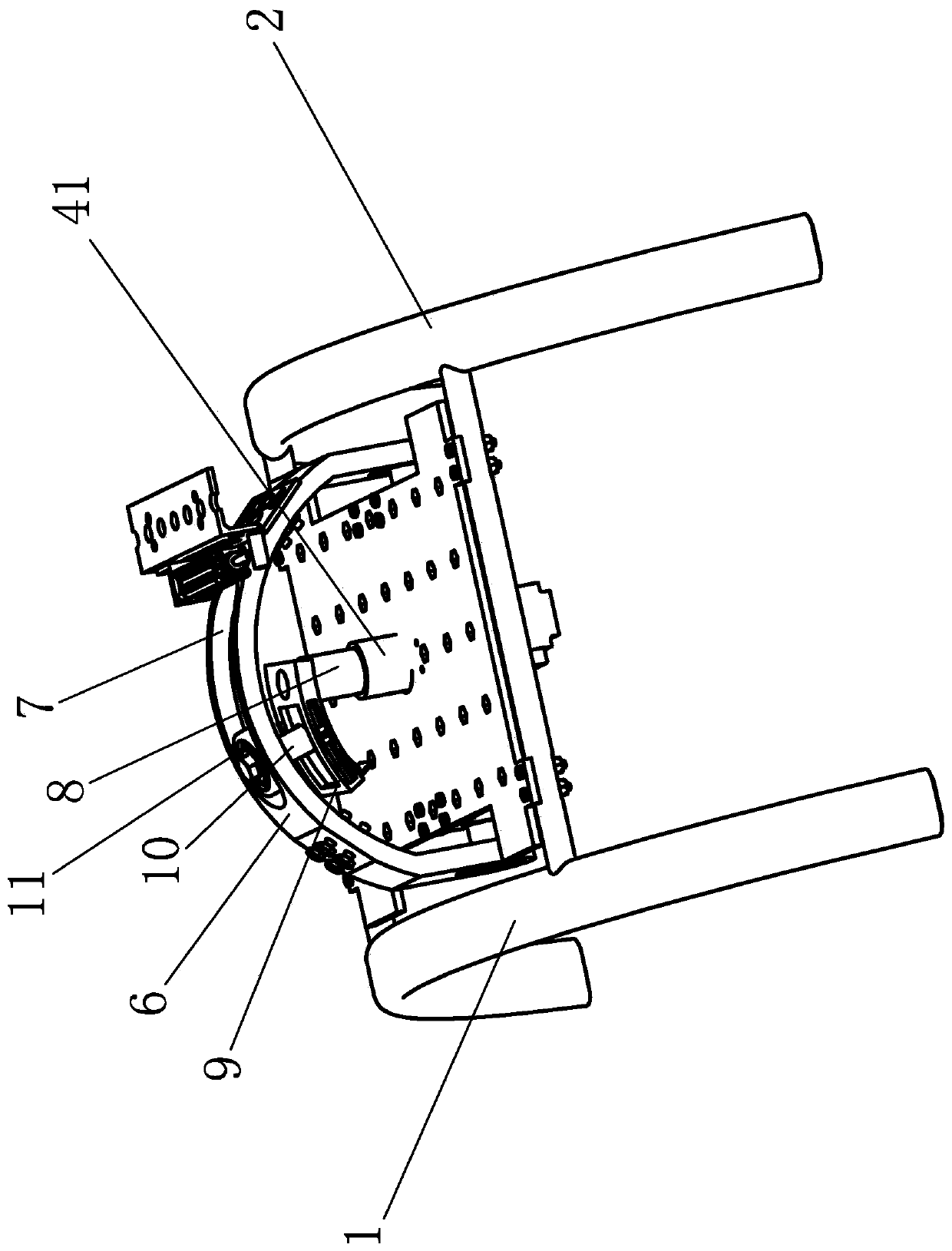
[0035] Such as figure 1 , figure 2 , image 3 , Figure 4 , Figure 5 and Figure 9 As shown, a rocking chair comprises a left outrigger 1 and a right outrigger 2, and the left outrigger 1 and the right outrigger 2 are fixedly connected by a connecting rod one 3 and a connecting rod two 4, and the connecting rod one 3 and the connecting rod two 4 is fixed with a bottom plate 5, which is characterized in that a plate-shaped U-shaped rocker 6 is arranged on the bottom plate 5. The cross-section of the U-shaped rocker 6 is rectangular and is formed by bending a plate-shaped sheet metal material. The U-shaped rocker 6 includes hinge part one 6a, hinge part two 6b and arc plate part 6c, hinge part one 6a is hinged with one side...


PUM


Abstract

The invention provides a rocking chair which realizes an automatic rocking function. The rocking chair comprises a bottom plate and is characterized in that a plate-shaped U-shaped rocker is arrangedon the bottom plate; the U-shaped rocker comprises a hinge part I, a hinge part II and an arc plate part; a swing mechanism capable of enabling the U-shaped rocker to swing front and back is arrangedon the bottom plate, a sliding groove is formed in the arc plate part of the U-shaped rocker, the swing mechanism comprises a rotating shaft arranged on the bottom plate in a rotating mode, a poking piece is fixed to the top end of the rotating shaft, a poking rod is fixed to the poking piece, and the rotating shaft is connected with a driving mechanism capable of enabling the rotating shaft to rotate; a first supporting seat and a second supporting seat are fixed to the arc plate part of the U-shaped rocker, a base is fixed to the first supporting seat and the second supporting seat, a firstkeel and a second keel are fixed to the base, seat cloth is arranged between the first keel and the second keel, and a backrest is further fixed between the first keel and the second keel. The rockingchair has the advantages of adjustable swing frequency, adjustable swing amplitude and the like.

Description

technical field [0001] The invention relates to a rocking chair, in particular to a rocking chair with an automatic rocking function. Background technique [0002] The rocking chair is a kind of chair that can rock back and forth. When people sit on the chair, they can rock back and forth along with the chair. It has a good experience and is deeply loved by people. The traditional rocking chair relies on the arc-shaped outriggers at the bottom to realize the front and rear swing. It does not have its own power source to realize the forward and backward swing. It needs to rely on manpower to realize its forward and backward swing, which reduces the user's sense of experience. In addition, When a traditional rocking chair rocks back and forth, its curved chair feet contact the ground alternately, which is easy to cause abrasion or noise to the ground, especially when it is placed on the bottom surface of the wooden floor at home, it is easy to damage Wooden floors cause wear ...

Claims


Application Information

Patent Timeline
Patent Type & Authority Applications(China)
IPC IPC(8): A47C3/025A47C7/44A47C7/46A47C7/00
CPCA47C3/0255A47C7/002A47C7/44A47C7/46
Inventor 李清阳
Owner 李清阳
Learn More