
Efficient servo sprayer
A sprayer and servo motor technology, applied in the direction of the spraying device, can solve the problems of small swing range, increased production cost, and complexity, and achieve the effects of reducing process time, ensuring spraying effect, and reducing production cost
- Summary
- Abstract
- Description
- Claims
- Application Information
AI Technical Summary
Problems solved by technology
Method used
Image

Examples
Embodiment 1
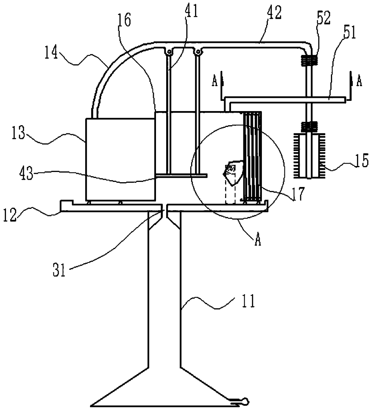
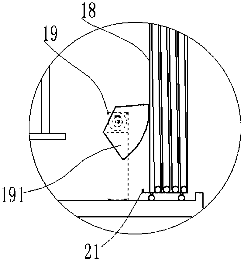
[0025] Such as figure 1 As shown, a high-efficiency servo sprayer includes a support 11 and a concave carriage 12 fixedly connected to the upper end of the support 11. The carriage 12 is provided with a sprayer 13 and a control device for improving the spray effect. 13 The spray end is connected to the air nozzle 15 via a hose 14. The control device includes a left and right control assembly for controlling the left and right movement of the sprayer 13, a swing control assembly for controlling the swing of the air nozzle 15, and the swing control assembly moves up and down via a telescopic assembly or The swing component swings left and right to drive the air nozzle 15 to reciprocate at a high speed to achieve efficient spraying; the left and right control components include a box 16 fixedly connected to one side of the sprayer 13, and a pulley is provided at the bottom of the box 16 and the sprayer 13, and the box 16 is far away from the sprayer. One end of sprayer 13 is prov...
Embodiment 2
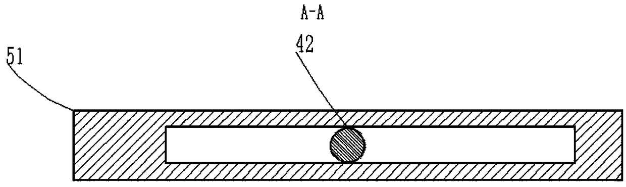
[0031] Such as figure 1 and figure 2As shown, the structure of this embodiment is basically the same as that of Embodiment 1, and the similarities will not be repeated. The difference is that a buffer device is provided on the telescopic assembly, and the buffer device includes a limiting plate 51 and a limiting flange 52 One end of the limiting plate 51 is fixedly connected to the upper end of the box body 16, the limiting plate 51 is provided with a limiting hole, one end of the swing arm 42 passes through the limiting hole, and two limiting flanges 52 are respectively arranged in the swinging arm 42 Two ends of a section perpendicular to the box body 16, springs are fixedly connected to one side close to each other in the limit flange 52, and the telescopic support 41 is an electric support. In this way, the buffer device provided can further reduce the position when the telescopic assembly moves up and down. The impact force at the maximum stroke, thereby increasing the ...
Embodiment 3
[0033] Such as figure 1 As shown, the structure of this embodiment is basically the same as that of Embodiment 1, and the similarities will not be repeated. The difference is that the support 11 is a hollow structure, and a through hole 31 is provided at the connection between the carriage 12 and the support 11. There is also a valve at the bottom of the support 11, so that the hollow structure support 11 can collect the release agent attached to the side wall of the box body 16 and the outer wall of the sprayer 13, and flow into the support 11 through the through hole 31. , taken out through the valve, and the usage rate of the release agent is increased through recycling, thereby further reducing the production cost.
PUM
 Abstract
Description
Claims
Application Information