Ultrasonic image optimization method and ultrasonic imaging equipment

A technology of ultrasonic image and optimization method, which is applied in ultrasonic/sonic/infrasonic diagnosis, ultrasonic diagnosis, infrasonic diagnosis, etc. It can solve the problem of not highlighting the key focus areas of ultrasonic images, and achieve the effect of improving the image display effect

Pending Publication Date: 2020-06-16
SHENZHEN MINDRAY BIO MEDICAL ELECTRONICS CO LTD
View PDF3 Cites 2 Cited by
  • Summary
  • Abstract
  • Description
  • Claims
  • Application Information

AI Technical Summary

Problems solved by technology

[0002] In clinical diagnosis, real-time ultrasound imaging has been widely used; in ultrasound examination, due to the influence of factors such as patient size and operation technique, the ultrasound image obtained by default may not be optimal, and doctors need to adjust a series of The parameters of the ultrasonic image can be optimized; specifically, after the entire ultrasonic image data is obtained, the ultrasonic image data of the entire field can be analyzed, and then parameters such as image gain and contrast can be adjusted according to the analysis results; this ultrasonic image optimization method can only be used for ultrasonic images. The image data of the whole field is analyzed and processed without highlighting the focus area of ​​the ultrasound image

Method used


Image

  • Ultrasonic image optimization method and ultrasonic imaging equipment
  • Ultrasonic image optimization method and ultrasonic imaging equipment
  • Ultrasonic image optimization method and ultrasonic imaging equipment

Examples


Embodiment Construction

[0019] In order to understand the characteristics and technical contents of the embodiments of the present application in more detail, the implementation of the embodiments of the present application will be described in detail below in conjunction with the accompanying drawings. The attached drawings are only for reference and description, and are not intended to limit the embodiments of the present application.

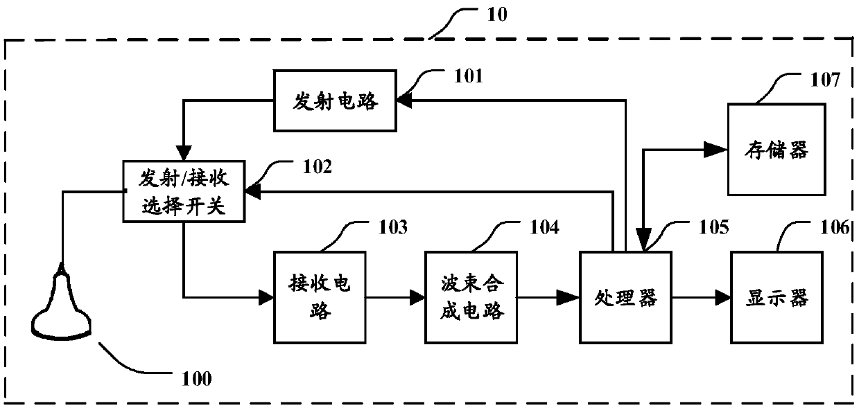
[0020] figure 1 It is a schematic structural block diagram of an ultrasonic imaging device in an embodiment of the present application. The ultrasonic imaging device 10 may include a probe 100 , a transmitting circuit 101 , a transmitting / receiving selection switch 102 , a receiving circuit 103 , a beam forming circuit 104 , a processor 105 and a display 106 . The transmitting circuit 101 can stimulate the probe 100 to transmit ultrasound to the target tissue; the receiving circuit 103 can receive the ultrasonic echo returned from the target tissue through the probe...


PUM


Abstract

The invention discloses an ultrasonic image optimization method and ultrasonic imaging equipment. The method comprises the following steps: transmitting ultrasonic waves to a target tissue, and receiving ultrasonic echoes returned from the target tissue so as to obtain ultrasonic echo data; acquiring ultrasonic whole-field image data according to the ultrasonic echo data; locating a target area from the ultrasonic whole-field image data through image recognition; and adjusting the image quality of the target area to enable the image quality of the target area to meet a first condition. Thus, after the target area is successfully positioned, the image quality of the target area can be adjusted so as to improve the image display effect of the target area in the ultrasonic whole-field image data.

Description

technical field [0001] The invention relates to ultrasonic image processing technology, in particular to an ultrasonic image optimization method and ultrasonic imaging equipment. Background technique [0002] In clinical diagnosis, real-time ultrasound imaging has been widely used; in ultrasound examination, due to the influence of factors such as patient size and operation technique, the ultrasound image obtained by default may not be optimal, and doctors need to adjust a series of The parameters of the ultrasonic image can be optimized; specifically, after the entire ultrasonic image data is obtained, the ultrasonic image data of the entire field can be analyzed, and then parameters such as image gain and contrast can be adjusted according to the analysis results; this ultrasonic image optimization method can only be used for ultrasound The image data of the whole field is analyzed and processed without highlighting the focus area of ​​the ultrasound image. Contents of t...

Claims


Application Information

Patent Timeline
Patent Type & Authority Applications(China)
IPC IPC(8): A61B8/00
CPCA61B8/5215
Inventor 刘杰李雷李庆鹏付强袁海锋
Owner SHENZHEN MINDRAY BIO MEDICAL ELECTRONICS CO LTD
Why Eureka
Try Eureka