
Wireless miniature fluorescent microscopic imaging device and application thereof

A fluorescence imaging and wireless technology, applied in the fields of application, analysis using fluorescence emission, image communication, etc., can solve problems such as difficulty in realizing free activities, not allowing researchers to observe experimental data in real time, wired connection, etc., to avoid deviations in research results Effect

Pending Publication Date: 2021-12-24
PEKING UNIV
View PDF6 Cites 0 Cited by
  • Summary
  • Abstract
  • Description
  • Claims
  • Application Information

AI Technical Summary

Problems solved by technology

Although some miniaturized fluorescence microscopes have been reported, most are wired solutions
The solution of wired connection adopts the method of connecting the microscope and the host computer with wires, which leads to a relatively large restriction on the free movement of animals, and some complex behaviors (such as the behavior of mice drilling holes) will be hindered, making it difficult to achieve complete freedom of movement. Deviations between experimental results and natural conditions
In addition, because wires are prone to entanglement, it is also difficult to do behavioral experiments on multiple mice (such as social behavior of multiple mice); the wireless connection solution is to store behavioral data on the back of the animal. implemented in the memory card
This solution does not allow researchers to observe the experimental data in real time during the experiment, but can only take out the SD card to read the data after the experiment is completed, resulting in the inability to effectively monitor the experimental results in real time

Method used


Image

  • Wireless miniature fluorescent microscopic imaging device and application thereof
  • Wireless miniature fluorescent microscopic imaging device and application thereof
  • Wireless miniature fluorescent microscopic imaging device and application thereof

Examples


Embodiment 1

[0063] Example 1: Wireless Miniature Fluorescent Microscopic Imaging Device

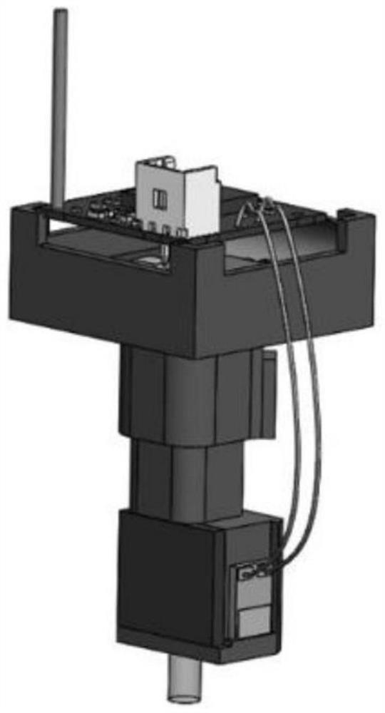
[0064] Such as figure 1 As shown, this embodiment provides a wireless miniature fluorescent microscopic imaging device, including a fluorescent imaging microscope, a wireless control unit, a wireless video transmission unit, a wireless video receiving unit and a video storage unit, wherein the wireless control unit includes a receiving control unit Components of end instruction and components of control fluorescence imaging microscope.

[0065] The miniature fluorescence microscope preferably includes a microscope illuminator, a number of independent optical components such as mirrors, micro-objective lenses, and filters, and an area array photodetector; the optical components are fixed together by a mechanical housing. Microscope illuminators are available with either monochromatic LEDs or fiber-coupled external lasers. By configuring different wavelength light sources and filter sets, fluorescenc...

Embodiment 2

[0077] Embodiment 2: the visual stimulation experiment of single mouse

[0078] The wireless miniature fluorescent microscopic imaging device in Example 1 was used to conduct a visual stimulation experiment of a single mouse.

[0079] The way the miniature microscope is fixed on the head of the mouse: All animal experiments were carried out in the animal center. Wild-type C57BL / 6 mice (male, 8-12 weeks old) were purchased from Vital River Laboratories (Beijing, China) and maintained on a 12 / 12-h reverse dark-light cycle. All experiments were performed during light cycling. Before surgery, mice were anesthetized with tribromoethanol (240 mg / kg, Sigma), and a craniotomy was performed on the primary visual cortex of the right hemisphere (Bregma coordinates: anteroposterior, -2.8 mm; middle, 2.5 mm; dorsoventral , 0.2 mm). After the craniotomy, a 1.8 mm diameter GRIN lens (Edmund Optics) was placed on the cortical surface without damaging the tissue. The gap between the GRIN l...

Embodiment 3

[0082] Embodiment 3: Photostimulation experiment of multiple mice

[0083] The light stimulation experiment of multiple mice was carried out using the wireless miniature fluorescent microscopic imaging device in Example 1.

[0084] Referring to the method in Example 2, the wireless miniature fluorescent microscopic imaging device in Example 1 was fixed on the heads of two mice.

[0085] Use a 50cm*50cm open field made of black acrylic, and paste black matte velvet to reduce the reflection on the inner wall, and install a circle of LED light strips at the bottom of the open field as a light stimulus. Since it is inconvenient to control the sight direction of the two mice in the free state, it is chosen to control the on and off of the LED light strip as the light stimulus. During the experiment, the LED light strip was turned on for 2 seconds and turned off for 18 seconds, and cycled sequentially. Each cycle time was 20 seconds, and the cycle was 20 times in total. At the same...


PUM


Abstract

The invention relates to the technical field of medical imaging, and relates to a miniature wireless fluorescence microscope and an imaging method. The total weight is 2.7 g, the total power consumption is about 0.7 W, a low-power-consumption wireless transmitting function and a remote control function are achieved under the condition of high integration level, and the characteristic that multiple devices work at the same time and do not interfere with one another is achieved. According to the imaging device, an acquired fluorescent microscopic image is transmitted to the receiving end through a 5.8 GHz radio-frequency signal, and is stored and played in real time by using a hard disk video recorder. The wireless control function can remotely control the gain value of the microscope, the brightness of an exciting light LED and the on-off of the microscope in the experiment process, so that image parameters and a standby function are regulated and controlled according to needs, and the microscope is turned off to enter a standby state in a time period without imaging so as to reduce power consumption.

Description

technical field [0001] The invention relates to a wireless miniature fluorescent microscopic imaging device and an application thereof, belonging to the field of biological monitoring equipment. Background technique [0002] Fluorescence microscope (Fluorescence microscope) is to irradiate the object under inspection with a light source of specific wavelength to make it emit fluorescence, and then observe the shape and location of the object under the microscope. In the biological field, the imaging of brain cells and blood vessels in freely moving animals is an important means of scientific research in related fields. Fluorescence microscopy can be used to study the absorption and transportation of intracellular substances, the distribution and localization of chemical substances, etc., which provides great help for exploring the structure and function of neural circuits. However, the traditional fluorescence microscope has a large total weight, takes up a lot of space, an...

Claims


Application Information

Patent Timeline
Patent Type & Authority Applications(China)
IPC IPC(8): A61B5/00A01K29/00H04N5/76H04N7/18
CPCA61B5/0071A61B5/0084A61B5/0013A61B5/002A61B5/4064A61B5/6868A61B5/6882A01K29/005H04N7/18H04N5/76A61B2503/40A61B2503/42
Inventor 李长辉李文昭马中天张晨王仰真
Owner PEKING UNIV
Learn More