Automatic device used for manufacturing of aluminum pot mold shell

An automatic device and mold technology, applied in the direction of manufacturing tools, casting molding equipment, metal processing equipment, etc., can solve the problems of relying on labor, lack of equipment, poor precision, etc.

Active Publication Date: 2020-06-16
兰溪太乙金属制品有限公司
View PDF13 Cites 1 Cited by
  • Summary
  • Abstract
  • Description
  • Claims
  • Application Information

AI Technical Summary

Problems solved by technology

[0006] The object of the present invention is to provide a kind of automation device that is used for the aluminum pan mold shell making, to solve the manufacturing method of the aluminum pan mold that is used now that proposes in the

Method used


Image

  • Automatic device used for manufacturing of aluminum pot mold shell
  • Automatic device used for manufacturing of aluminum pot mold shell
  • Automatic device used for manufacturing of aluminum pot mold shell

Examples


Embodiment 1

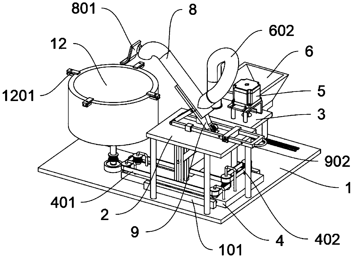
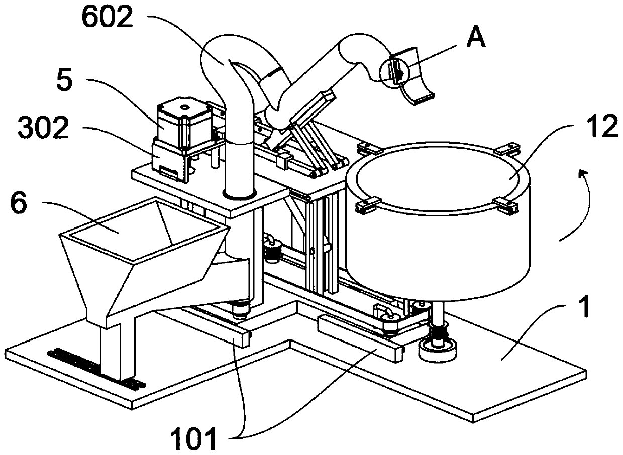
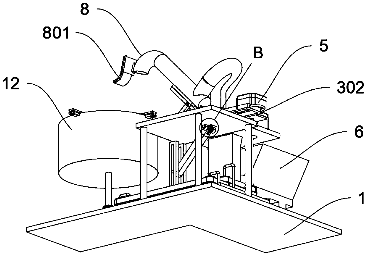
[0033] see Figure 1 to Figure 3 and Figure 5 to Figure 8 , an embodiment provided by the present invention: an automatic device for making an aluminum pot mold shell, including a bottom plate 1; the top of the bottom plate 1 is connected with a top plate 2 through a column; wherein, the middle of the top plate 2 is provided with an upward rotation through a rotating shaft. The rod 9 and the lower rotating rod 10, and the upper rotating rod 9 and the lower rotating rod 10 are all connected by a key to set the gear 11 to rotate synchronously; the top of the upper rotating rod 9 is fixed with a delivery pipe 8 by bolts, and the flexible pipe 602 passes through the clamp The seal is arranged on the top side of the rear end of the delivery pipe 8; wherein, the delivery pipe 8 includes a smear plate 801, the smear plate 801 is an arc-shaped structure and a strip-shaped hole is opened on one side, and the smear plate 801 can be fixed on the delivery pipe by bolts. The outer end of...

Embodiment 2

[0036] On the basis of Example 1, please refer to Figure 1 to Figure 4, a kind of embodiment that the present invention provides: a kind of automation device that is used for the aluminum pan mold shell to make, movable bottom plate 4 includes double-sided synchronous belt 401, transmission synchronous belt 402 and transmission shaft 403; Movable bottom plate 4 top moves through rotating shaft There are three sets of single-layer synchronous wheels and one set of two-layer synchronous wheels, and a double-sided synchronous belt 401 is arranged outside the synchronous wheels; a transmission shaft 403 is arranged on the top of the movable bottom plate 4 through bearing activities, and a synchronous belt is arranged on the outside of the transmission shaft 403 to cooperate with the transmission The synchronous belt 402 is kinematically connected with the two-layer synchronous wheels; the top of the movable bottom plate 4 is integrally provided with a vertical rod structure and is...


PUM


Abstract

The invention discloses an automatic device used for manufacturing of an aluminum pot mold shell, and relates to the technical field of mold manufacturing. The problems that the manufacturing method used for an aluminum pot mold at preset quite depends on manpower, precision is poor, and the functions of intermittently feeding quantitative cement onto gauze, driving gauze to rotate and floating cement on gauze are not achieved are solved. The automatic device used for manufacturing of the aluminum pot mold shell comprises a bottom plate; a top plate is connected and arranged at the top of thebottom plate through stand columns; a moving top plate is arranged on one side of the top plate through a sliding structure in a sliding manner; and through the arrangement of an upper rotating rod and a lower rotating rod, the function of synchronous material clamping is provided for the shell manufacturing device, a conveying pipe can be lifted at the same time through pull rod movement, an aluminum pot can be replaced conveniently, a moving bottom plate is pulled away, and through contact of a transmission mechanism of a pot rack and motion connection of the pot rack, the pot rack can be stripped and cleared conveniently.

Description

technical field [0001] The invention relates to the technical field of mold making, in particular to an automatic device for making aluminum pot mold shells. Background technique [0002] Most of the aluminum pot mold shells now generally apply a certain amount of cement evenly on the gauze. After the workers apply the cement evenly on the gauze, the workers can wait for the cement to solidify and form, and complete the production of the aluminum pot mold shell, which usually requires workers. The cement is applied step by step on the inner surface of the mold pot by hand, and the cement is paved with tools to complete the production. [0003] After searching for example, the patent No. CN103192059A discloses a gravity casting method for an energy-saving aluminum pot for an electromagnetic cooker, which includes: one, preparing a stainless iron plate cast on the bottom of the pot; Special mold; 3. Gravity casting process, wherein, the gravity casting process includes: (1) f...

Claims


Application Information

Patent Timeline
IPC IPC(8): B22C13/08
CPCB22C13/08
Inventor 张藝龄
Owner 兰溪太乙金属制品有限公司
Why Eureka
Try Eureka