Eureka AIR delivers breakthrough ideas for toughest innovation challenges, trusted by R&D personnel around the world.

Building same-floor water drainage collection device

A same-layer drainage and concentrator technology, which is applied in the direction of buildings, drainage structures, waterway systems, etc., can solve the problems of increasing the water flow noise of the drainage riser, the decrease of the drainage capacity of the drainage riser, and the large air flow disturbance of the drainage riser, etc., to achieve drainage Smooth, increase drainage capacity, reduce the effect of riser water flow noise

Active Publication Date: 2020-06-16
深圳市新星联合管道有限公司
View PDF6 Cites 3 Cited by
  • Summary
  • Abstract
  • Description
  • Claims
  • Application Information

AI Technical Summary

Problems solved by technology

However, the airflow in the drainage riser pipe and the drainage horizontal pipe of the existing building drainage concentrator on the same floor is not smooth, which greatly disturbs the air flow in the drainage riser pipe, resulting in large pressure fluctuations, increasing the water flow noise of the drainage riser pipe, causing The drainage capacity of the drainage standpipe is reduced, and it is easy to block at the confluence of the drainage riser pipe and the drainage horizontal pipe, which needs to be cleaned frequently

Method used


Image

  • Building same-floor water drainage collection device
  • Building same-floor water drainage collection device
  • Building same-floor water drainage collection device

Examples


Embodiment Construction

[0024] It should be noted that, in the case of no conflict, the embodiments of the present invention and the features in the embodiments can be combined with each other. The present invention will be described in detail below with reference to the accompanying drawings and examples.

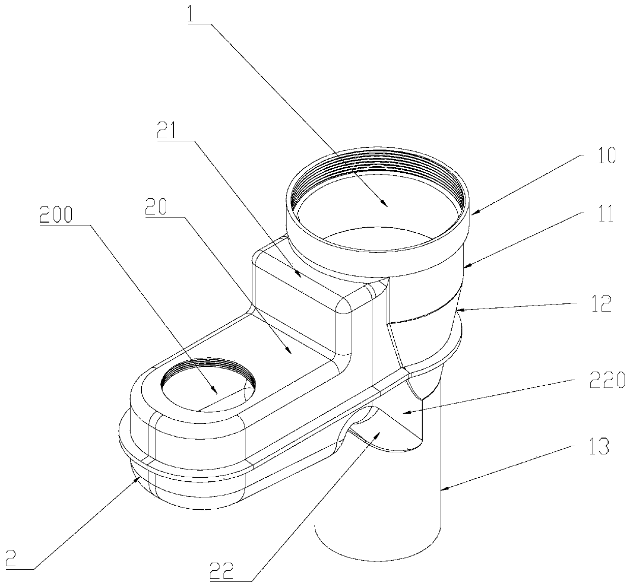
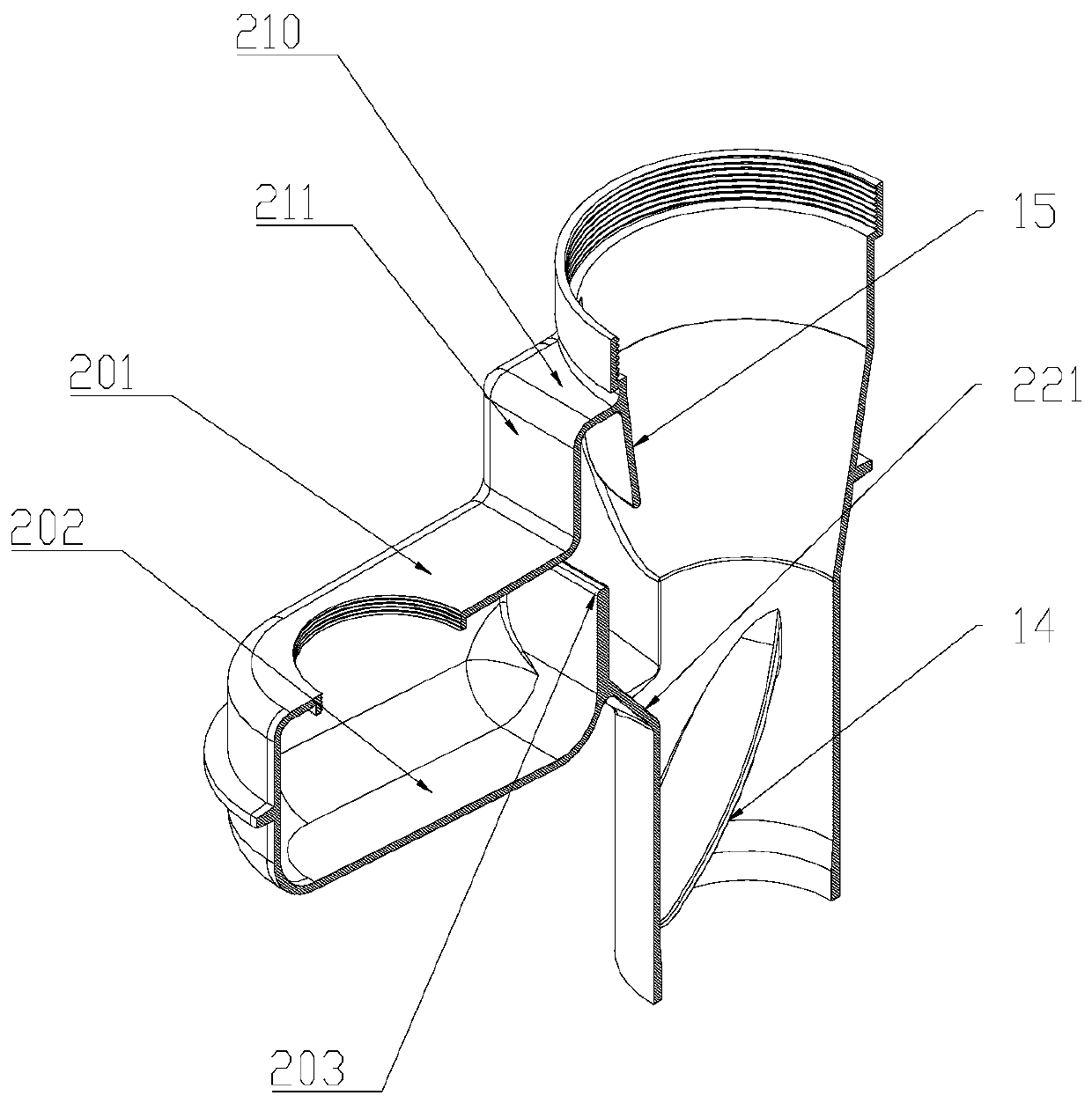
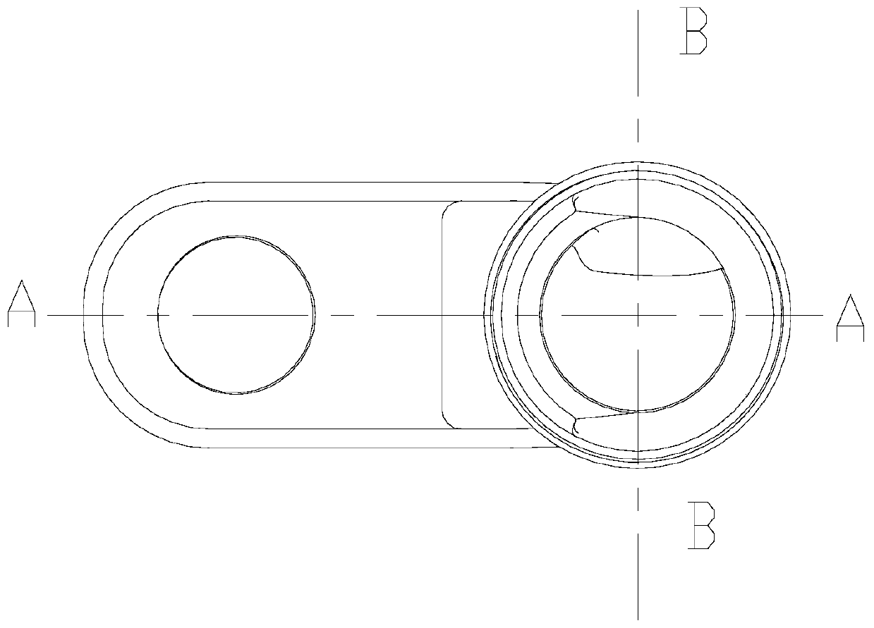
[0025] Such as figure 1 As shown, the present invention provides a drainage concentrator on the same floor of a building, including a vertical drainage pipe 1 and a horizontal drainage pipe 2 , the horizontal drainage pipe 2 intersects with the vertical drainage pipe 1 , and the horizontal drainage pipe 2 and the vertical drainage pipe 1 are integrally formed. Drain riser 1 includes straight pipe expansion section 11, funnel expansion section 12, and lower drainage straight pipe connection section 13 connected to each other from top to bottom. The diameter of straight pipe expansion section 11 is larger than the diameter of lower drainage straight pipe connection section 13. 12 large ends are co...


PUM


Abstract

The invention discloses a building same-floor water drainage collection device. A water drainage groove draining water towards a water drainage vertical pipe in an inclined manner is formed in the collection position of a water drainage transverse pipe and the water drainage vertical pipe. A water seal baffle is arranged in the water drainage transverse pipe. The water drainage transverse pipe comprises a water accumulation cavity and a buffer cavity. The water accumulation cavity is formed in one side of the water seal baffle, and the water drainage groove is formed in the other side of the water seal baffle. The buffer cavity is located between the water accumulation cavity and the water drainage groove and is higher than the water accumulation cavity and the water drainage groove. The water accumulation cavity communicates with the buffer cavity. The buffer cavity communicates with the water drainage groove. The water drainage groove and the water accumulation cavity are converged at the lower end of the buffer cavity. The water drainage groove intersects with the water drainage vertical pipe. The buffer cavity intersects with the water drainage vertical pipe. By means of the building same-floor water drainage collection device, building same-floor water drainage can be achieved, gas flow in the water drainage vertical pipe and gas flow in the water drainage transverse pipecan be integrated and unblocked, the pressure fluctuation of the water drainage vertical pipe is effectively reduced, the water flow speed of the water drainage vertical pipe is decreased, the water drainage capacity of the water drainage vertical pipe is substantially increased, and the water flow noise of the vertical pipe is reduced.

Description

technical field [0001] The invention relates to the field of building same-floor drainage, in particular to a building same-floor drainage collector. Background technique [0002] The same-floor drainage of the building means that the drainage horizontal pipes on the same floor do not pass through the floor, and are connected to the drainage vertical pipes on the same floor. If there is a situation that needs to be cleaned and dredged, a drainage method that can solve the problem in this layer of casing. Compared with the traditional drainage method of separate floors, the most fundamental concept change of the same-floor drainage scheme is to completely get rid of the shackles between adjacent floors through the rational layout of the pipelines in this floor, and avoid the encroachment of the lower floor space by the horizontal drainage pipes. And caused a series of troubles and hidden dangers. However, the airflow in the drainage riser pipe and the drainage horizontal pi...

Claims


Application Information

Patent Timeline
Patent Type & Authority Applications(China)
IPC IPC(8): E03C1/122E03C1/298E03F5/04
CPCE03C1/122E03C1/298E03C2201/60E03F5/0407Y02A30/60
Inventor 殷志
Owner 深圳市新星联合管道有限公司
Why Eureka
Eureka Blog
Learn More