
A Combined Structure for Shock Absorption and Collapse Prevention

A technology of combined structure and frame structure, applied in the direction of earthquake resistance, building components, building structure, etc., can solve the problems of falling off parts without protective measures, lack of seismic defense line, low redundancy of frame structure, etc., to achieve broad market application prospects , saving materials, easy to obtain the effect of

Active Publication Date: 2021-04-06
QINGDAO TECHNOLOGICAL UNIVERSITY +1
View PDF8 Cites 0 Cited by
  • Summary
  • Abstract
  • Description
  • Claims
  • Application Information

AI Technical Summary

Problems solved by technology

[0007] According to the deficiencies of the prior art above, the present invention provides a joint structure for shock absorption and collapse prevention, which solves the problems of low redundancy of frame structure, lack of anti-seismic defense lines and no protective measures for falling off parts

Method used


Image

  • A Combined Structure for Shock Absorption and Collapse Prevention
  • A Combined Structure for Shock Absorption and Collapse Prevention
  • A Combined Structure for Shock Absorption and Collapse Prevention

Examples


Embodiment 1

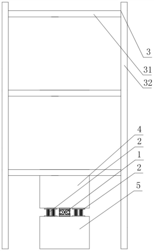
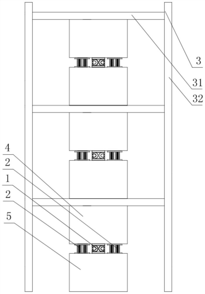
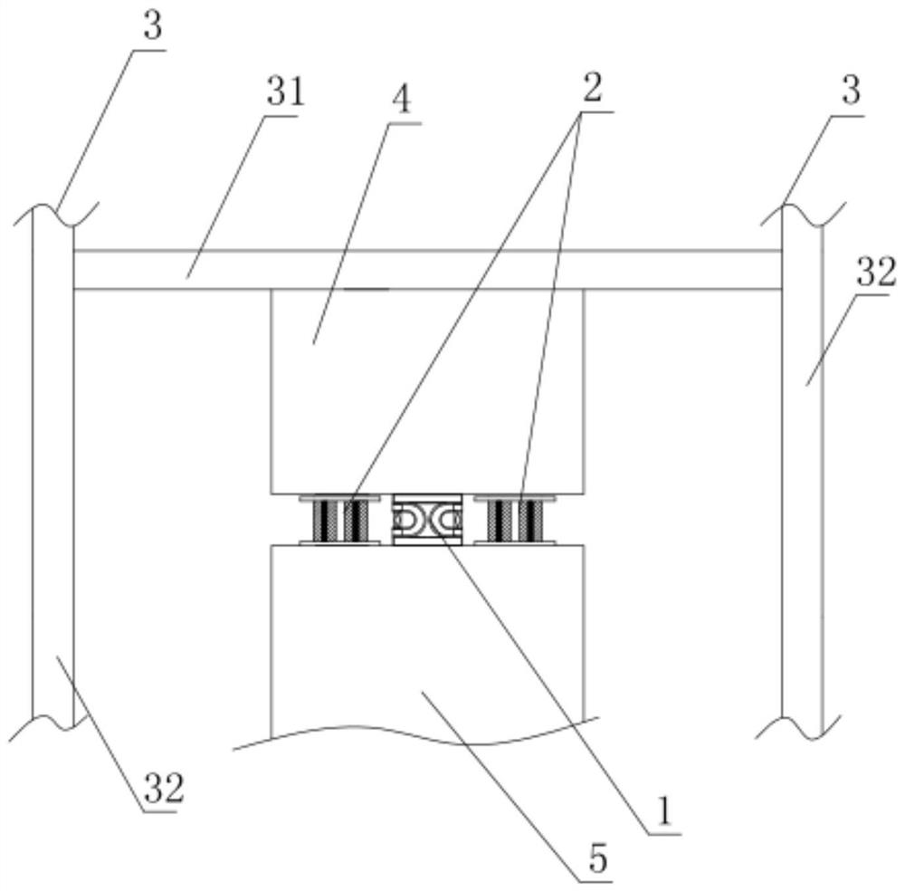
[0046] Such as Figure 1 ~ Figure 3 As shown, a joint structure for shock absorption and anti-collapse described in the present invention, the joint structure includes a step-by-step yield damper 1 and an anti-collapse steel pier 2, and the step-by-step yield damper 1 and the anti-collapse steel pier 2 Both are detachably connected between the upper wall pier 4 and the lower wall pier 5 as lateral force-resisting members in the frame structure 3 through an inter-column type connection, the upper wall pier 4 is connected to the frame beam, and the lower wall pier 5. It is connected with the ground or the floor, and the staged yield damper 1 and the anti-collapse steel pier 2 are connected by inter-column type in the frame structure 3, which improves the redundancy of the main structure and does not affect the normal use function of the main structure. Does not occupy the facade space of the main structure, the frame structure 3 is composed of frame beams 31 and frame columns 32...

Embodiment 2

[0066] There is another structure for reinforcing ribs on the web 22 of the anti-collapse steel pier 2 in Embodiment 1, that is, a number of ribs are welded on both sides of the web 22 of the anti-collapse steel pier 2 to be perpendicular to the web 22 and arranged at intervals. The reinforcement ribs B222 on each web 22 are arranged in the following ways from the front to the rear: the upper end is inclined backward, the upper end is vertically arranged, and the upper end is inclined forward, and the upper end is inclined backward and the upper end is inclined forward. The reinforcing ribs B222 are respectively at an angle of 45° with the reinforcing ribs B vertically arranged in the middle, as Figure 10 shown.

[0067] The vertical reinforcing rib B222 in the middle divides the web 22 into two front and rear regions, which can have a good supporting effect on the vertical concentrated load.

[0068] The reinforcing rib B222 can not only improve the local stability of the w...


PUM


Abstract

The invention belongs to the technical field of civil engineering, and particularly relates to a joint structure for shock absorption and anti-collapse. The joint structure is arranged between an upper wall pier and a lower wall pier and includes a staged yield damper and an anti-collapse steel pier. The staged yield damper It includes an outer connecting plate and an inner component. The outer connecting plate is arranged on the outside of the inner component. The inner component includes an outer U-shaped steel plate, an inner U-shaped steel plate and a shearing steel plate. The shearing steel plate straddles the two arms of the inner U-shaped steel plate. In between, the outer circumference of the inner U-shaped steel plate is provided with an outer U-shaped steel plate at intervals, and the openings of the inner U-shaped steel plate and the outer U-shaped steel plate have the same opening orientation; the anti-collapse steel pier includes two outer steel plates that are The web plates are arranged in parallel and at intervals, and the upper end of the anti-collapse steel pier and the upper wall pier are arranged at intervals. The invention can successively yield and consume energy according to the degree of earthquake from weak to strong, and is easy to disassemble and replace, forms a safe space near the wall piers, and avoids the continuous collapse of wall piers and frame beams.

Description

technical field [0001] The invention belongs to the technical field of civil engineering, and in particular relates to a joint structure for shock absorption and collapse prevention. Background technique [0002] Reinforced concrete frame structure has the advantages of flexible building layout, good integrity, clear force transmission path, and light structure weight. It gradually occupies a large proportion of housing structures and multi-storey public buildings in my country. In the reinforced concrete frame structure system, the frame column bears the additional axial force generated by the shear force, gravity and overturning moment from the upper floor. As a result, the expected damage mode of "strong column and weak beam" is difficult to realize, and then develops into a "column-hinge" yield mechanism, forming a cambium collapse mode. The seismic performance of the frame structure is better under small earthquakes, but the collapse rate is extremely high in the extre...

Claims


Application Information

Patent Timeline
Patent Type & Authority Patents(China)
IPC IPC(8): E04B1/98E04H9/02E04B1/343
CPCE04B1/34315E04B1/34326E04B1/98E04H9/021
Inventor 许卫晓程扬杨伟松于德湖张纪刚
Owner QINGDAO TECHNOLOGICAL UNIVERSITY
Learn More