
Elevating rotating device and electronic equipment

A technology for rotating devices and electronic equipment, which is applied to transmission devices, mechanical equipment, electromechanical devices, etc., and can solve the problems of large volume of lifting rotating devices.

Inactive Publication Date: 2021-04-27
AAC OPTICS (CHANGZHOU) CO LTD
View PDF6 Cites 0 Cited by
  • Summary
  • Abstract
  • Description
  • Claims
  • Application Information

AI Technical Summary

Problems solved by technology

[0005] The purpose of the present invention is to provide a lifting rotating device and electronic equipment to solve the technical problem that the lifting rotating device is too large in the prior art

Method used


Image

  • Elevating rotating device and electronic equipment
  • Elevating rotating device and electronic equipment
  • Elevating rotating device and electronic equipment

Examples


Embodiment 1

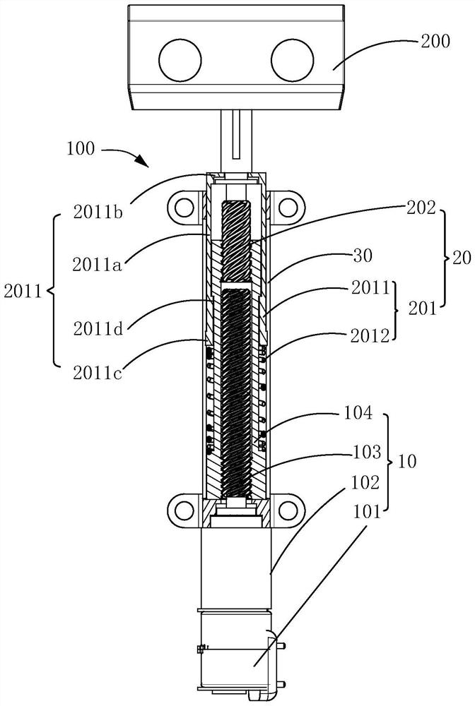
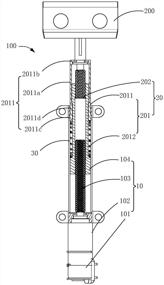
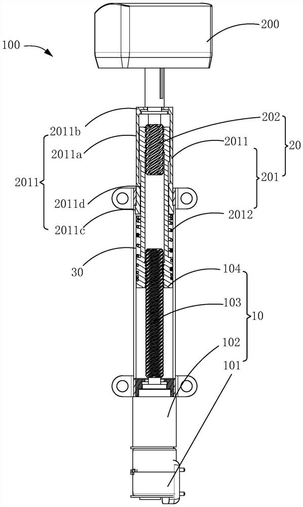
[0031] Embodiment 1 of the present invention provides an elevating rotating device 100 for driving an electronic mechanism 200 to elevate and rotate, please refer to figure 1 As shown, the lifting rotating device 100 includes a driving mechanism 10 and a transmission mechanism 20. After the driving mechanism 10 provides power to the transmission mechanism 20, the transmission mechanism 20 drives the electronic mechanism 200 to lift and rotate. The driving mechanism 10 includes a motor 101, a reduction box 102 connected to the motor 101, a drive shaft 103 connected to the reduction box 102, and a lifting cylinder 104 sleeved on the driving shaft 103. The lifting cylinder 104 can be lifted along the axial direction of the driving shaft 103 Movement, specifically, the driving shaft 103 is preferably a screw, and the lifting cylinder 104 is threadedly matched with the driving shaft 103. When the motor 101 drives the driving shaft 103 to rotate through the reduction box 102, the lif...

Embodiment 2

[0050] Embodiment 2 of the present invention provides an electronic device, which includes an electronic mechanism 200 and an elevating rotating device 100 connected to the electronic mechanism 200 .

[0051] Specifically, for the structure of the lifting rotating device 100, refer to Embodiment 1. In an optional implementation manner, the electronic mechanism 200 is a camera mechanism, and the camera mechanism includes a camera.

Embodiment 3

[0053] Embodiment 3 of the present invention provides a terminal device, please refer to Figure 10 As shown, the terminal device includes a housing 300 with a storage cavity 3001 and an electronic device 400. The electronic device 400 includes an electronic mechanism 200 and an elevating rotating device 100 connected to the electronic mechanism 200. The electronic device 400 is installed in the housing In the cavity 3001, the casing 300 is penetratingly provided with a port 3002 communicating with the receiving cavity 3001 for the passage of the electronic mechanism 200. The electronic mechanism 200 is arranged opposite to the port 3002, so The electronic mechanism 200 can be extended from the opening 3002 to the outside of the storage cavity 3001 and retracted into the storage cavity 3001 through the lifting and rotating device 100, and the opening 3002 is vertical to the electronic mechanism. The width of the telescopic direction of 200 is greater than the width of the elec...


PUM


Abstract

The invention relates to the technical field of electronic equipment, in particular to an elevating rotating device and electronic equipment using the elevating rotating device. In the lifting rotating device of the present invention, the driving mechanism includes a driving shaft and a lifting cylinder sleeved on the driving shaft; the transmission mechanism includes a linear transmission assembly and a rotating shaft; the linear transmission assembly includes a limit cylinder sleeved outside the upper end of the lifting cylinder And the elastic member connected between the limiting cylinder and the lifting cylinder; one end of the rotating shaft is sleeved in the upper end of the lifting cylinder, and the other end of the rotating shaft protrudes from the top of the limiting cylinder to connect with the electronic mechanism, and the rotating shaft is connected to the The top of the limiting cylinder can be rotatably connected; through the above method, the drive shaft for linear lifting motion and the lifting cylinder and the rotating shaft for rotating motion are coaxially arranged, which reduces the volume of the entire device and is conducive to the miniaturization of the device. At the same time, the coaxial setting of the drive shaft, the lifting cylinder and the rotating shaft is conducive to optimizing the force on the device and increasing the output thrust of the device.

Description

【Technical field】 [0001] The invention relates to the technical field of electronic equipment, in particular to an elevating rotating device and electronic equipment using the elevating rotating device. 【Background technique】 [0002] When electronic products in the prior art use information collection equipment, one or more motors push the camera of the information collection equipment to perform linear lifting and rotating movements, thereby realizing the lifting and rotating functions of the camera. [0003] The lifting and rotating device in the prior art generally adopts the way that the lifting shaft and the rotating shaft are arranged in parallel in space, so that the lifting and rotating device in the prior art has the problem of too large volume, which limits the application of the lifting and rotating device. [0004] Therefore, it is necessary to provide a new lifting and rotating device to solve the above-mentioned problems in the prior art. 【Content of inventi...

Claims


Application Information

Patent Timeline
Patent Type & Authority Patents(China)
IPC IPC(8): F16M11/06F16M11/18F16M11/28H02K7/10G03B17/56
CPCF16M11/06F16M11/18F16M11/28H02K7/10G03B17/56F16H2025/204F16H2025/2075
Inventor 翟晓岗苏蔚马冬管明章
Owner AAC OPTICS (CHANGZHOU) CO LTD
Learn More