Laser dust detector correction device and correction method

A technology of calibration device and calibration method, which is applied to measurement devices, scientific instruments, analysis of suspensions and porous materials, etc. Scope of production use, reliable performance, simple structure effect

Pending Publication Date: 2020-06-16
CHINA JILIANG UNIV
View PDF0 Cites 0 Cited by
  • Summary
  • Abstract
  • Description
  • Claims
  • Application Information

AI Technical Summary

Problems solved by technology

The standard dust measurement method stipulated in my country's national standard is the weighing detection method, which has the advantages of the most accurate measurement and wide application range, but the measurement time is long, the process is cumbersome, and it is not easy to combine with other treatment processes; the laser dust detection method has advantages compared with the weighing method. The operation is simple, the detection time is short, and it is easy to combine with other treatment processes, etc., but other factors such as humidity will affect its measured value. Therefore, in order to ensure the accuracy of the laser method that can be measured in time, it is very necessary to calibrate the laser method dust measuring instrument
[0004] At present, there are two main types of calibration for laser dust detectors in different environments. One is to select the empirical correlation degree K value of the corresponding particle under the corresponding temperature and humidity based on the experimental data of related papers. Although this method takes the shortest time, it cannot Accurate dust concentration is measured with the change of the environment; the other is to calibrate according to the dust particle counting device, the precision is higher with the simple calibration, but it takes too long

Method used


Image

  • Laser dust detector correction device and correction method
  • Laser dust detector correction device and correction method

Examples


Embodiment Construction

[0019] The present invention will be described in further detail below in conjunction with the accompanying drawings and specific embodiments.

[0020] refer to figure 1 , figure 2 .

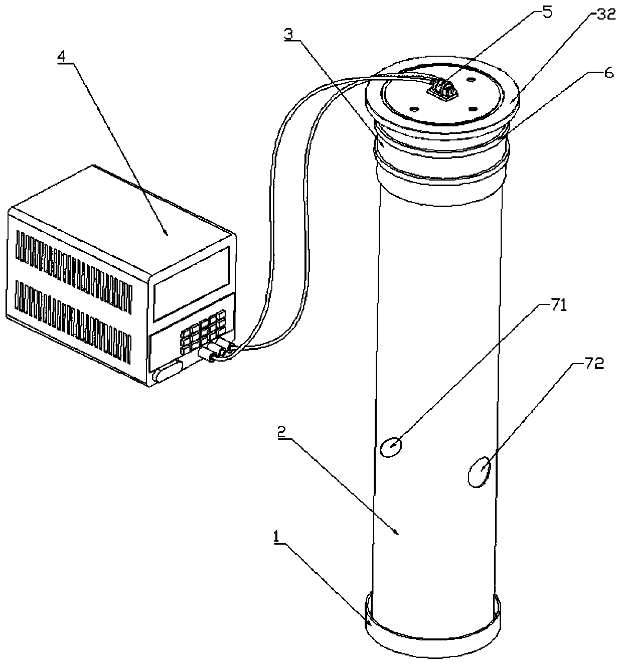
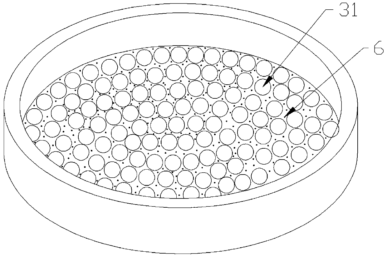
[0021] Such as figure 1 As shown, a calibration device and calibration method for a laser dust detector, the device is as follows, including: a base (1), characterized in that it also includes a detection chamber (2), a dust chamber (3), and a vibration machine (5), vibrating screen (6), buffer glass beads (31), dust cover (32), DC vibrator (5), the bottom of the magnetic base (1) is provided with a detection port (7), including: Laser method detection hole (71), weighing method detection hole (72); the detection chamber (2) is embedded in the base (1), the wall is provided with a detection hole (4), and the dust generation chamber (3) is connected to Above the detection chamber (2).

[0022] Preferably, the base (1) and the detection chamber (2) are circular in shape and the detection cha...


PUM


Abstract

The invention discloses a laser dust detector correction device and correction method. The device comprises a base, a detection chamber, a dust generating chamber and an adjustable stabilized voltagesupply. The base is a tray with the diameter slightly larger than that of the detection chamber, the detection chamber can be directly arranged on the base, and dust can be recycled conveniently; thedetection chamber is made of a transparent organic glass tube, and two detection holes are formed in the tube wall of the detection chamber; the interior of the dust generating chamber is hollow, a screen is arranged at the bottom, and a cover plate with a vibrator is arranged at the top; buffering glass beads are arranged in the dust generating chamber to achieve the buffering effect before dustfalls down. The adjustable stabilized voltage supply is used for adjusting different voltages and creating environments with different dust concentrations; the base is connected with the detection chamber through placement; and the detection chamber and the dust generating chamber are in flexible connection through a PVC film. The device is simple in structure, diverse in function, reliable in performance, low in manufacturing cost and convenient for large-scale production and use.

Description

technical field [0001] The invention relates to the technical field of laser dust detection equipment, in particular to a calibration device and a calibration method for a laser dust detector. [0002] technical background [0003] In the past 10 years, with the deepening of people's understanding of dust, the level of dust concentration has also become the focus of attention of people all over the world. With the development of society, the dust concentration detection technology is also constantly improving, showing more and more excellent performance. There are many dust concentration detection technologies currently used at home and abroad, and dust concentration detection technologies can be classified from different angles. According to whether the dust in the air is collected and sampled during the dust measurement process, the dust measurement method can be divided into sampling method and non-sampling method; according to whether the dust measurement can be directly...

Claims


Application Information

Patent Timeline
IPC IPC(8): G01N15/06
CPCG01N15/06G01N15/075
Inventor 陈永良金汉黄冬梅李海航李恩波
Owner CHINA JILIANG UNIV
Why Eureka
Try Eureka