Radar vertical accumulation liquid water content inversion method
A technology for liquid water content and liquid water content, which is used in measuring devices, radio wave measurement systems, and radio wave reflection/re-radiation, etc. The effect of improving accuracy
Active Publication Date: 2020-06-16
INNER MONGOLIA UNIV OF TECH
7 Cites 5 Cited by
AI-Extracted Technical Summary
Problems solved by technology
[0004] The purpose of the embodiment of the present invention is to provide a radar vertical accumulation liquid water cont...
Abstract
The invention discloses a radar vertical accumulation liquid water content inversion method, and the method the following steps: using a first radar to obtain a first echo, and using a second radar toobtain a second echo so as to obtain first echo data and second echo data; respectively extracting the first echo data and the second echo data to obtain a first reflectivity factor of each samplingpoint and a second reflectivity factor of each sampling point; fusing the first reflectivity factor and the second reflectivity factor of each sampling point by using a fuzzy logic algorithm to obtaina target reflectivity factor of each sampling point; and performing calculating based on the target reflectivity factor of each sampling point to obtain the vertically accumulated liquid water content. According to the invention, two radars with different working wavelengths are utilized to obtain the detection data, and the fuzzy logic algorithm is utilized to fuse the reflectivity factors in the obtained detection data, so the liquid water content in the cloud calculated based on the reflectivity factors is more accurate, and the accuracy of forecasting the strong weather process is improved.
Application Domain
Radio wave reradiation/reflectionICT adaptation
Technology Topic
Liquid waterReflectivity +7
Image
Examples
- Experimental program(1)
Example Embodiment
[0031] Various solutions and features of the present application are described here with reference to the drawings.
[0032] It should be understood that various modifications can be made to the embodiments applied herein. Therefore, the above description should not be regarded as a limitation, but merely as an example of an embodiment. Those skilled in the art will think of other modifications within the scope and spirit of this application.
[0033] The drawings included in the specification and constituting a part of the specification illustrate the embodiments of the application, and together with the general description of the application given above and the detailed description of the embodiments given below, are used to explain the application principle.
[0034] These and other characteristics of the present application will become apparent from the following description of preferred forms of embodiments given as non-limiting examples with reference to the accompanying drawings.
[0035] It should also be understood that although the application has been described with reference to some specific examples, those skilled in the art can surely implement many other equivalent forms of the application, which have the features described in the claims and are therefore located here Within the limited scope of protection.
[0036] When combined with the drawings, the above and other aspects, features and advantages of the present application will become more apparent in view of the following detailed description.
[0037] Hereinafter, specific embodiments of the present application will be described with reference to the accompanying drawings; however, it should be understood that the applied embodiments are merely examples of the present application, which can be implemented in various ways. Well-known and/or repeated functions and structures have not been described in detail to avoid unnecessary or redundant details from obscuring the application. Therefore, the specific structural and functional details applied herein are not intended to be limiting, but merely serve as the basis and representative basis of the claims to teach those skilled in the art to use the present invention in a variety of ways with substantially any suitable detailed structure. Application.
[0038] This specification may use the phrases "in one embodiment," "in another embodiment," "in yet another embodiment," or "in other embodiments," which can all refer to the same according to the application. Or one or more of the different embodiments.
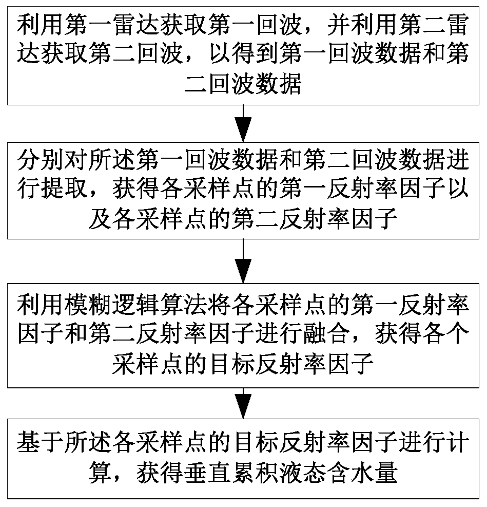
[0039] The embodiment of the present invention provides a radar vertical accumulation liquid water content inversion method, such as figure 1 As shown, including the following steps:
[0040] Step 1: Use the first radar to obtain the first echo, and use the second radar to obtain the second echo to obtain the first echo data and the second echo data;
[0041] Step 2: Extract the first echo data and the second echo data respectively to obtain the first reflectivity factor of each sampling point and the second reflectivity factor of each sampling point;
[0042] Step 3: Use fuzzy logic algorithm to fuse the first reflectivity factor and the second reflectivity factor of each sampling point to obtain the target reflectivity factor of each sampling point;
[0043] Step 4: Calculate based on the target reflectivity factor of each sampling point to obtain the vertical cumulative liquid water content.
[0044] The embodiment of the present invention uses two radars with different working wavelengths to obtain detection data, and uses a fuzzy logic algorithm to fuse the reflectivity factors in the detection data obtained by the two radars, so that the liquid content in the cloud calculated based on the reflectivity factors Water volume is more accurate, which improves the accuracy of forecasting strong weather processes
[0045] In the specific implementation process of the embodiment of the present invention, the first radar and the second radar are two radars with different working wavelengths. The working wavelength of the first radar is greater than the working wavelength of the second radar. Specifically, the first radar may be a centimeter wave. For radar, the second radar can be a millimeter wave radar; or the first radar is a meter wave radar and the second radar is a centimeter wave radar. It can be selected according to actual needs and when placing the first radar and the second radar, The first radar and the second radar are arranged at a predetermined distance apart. When two radars are used for observation, the crosstalk between electromagnetic waves and the maximum unambiguous distance that can be observed by the radar are taken into consideration. Therefore, when placing the radar, refer to the minimum detection distance of the first radar, so that the distance between the two radars is not less than the first. The minimum detection distance of the radar can effectively avoid the crosstalk between electromagnetic waves.
[0046] In the following, the first radar is a centimeter wave radar (X-band rain measuring radar), and the second radar is a millimeter wave mine (that is, Ka-band cloud measuring radar) as an example for specific description. The wavelength of the millimeter wave needs to be 2mm~10mm, the wavelength range of centimeter wave should be 11mm~300mm. The specific implementation steps are:
[0047] S1. Set the working mode of X-band rain measurement radar, which specifically includes:
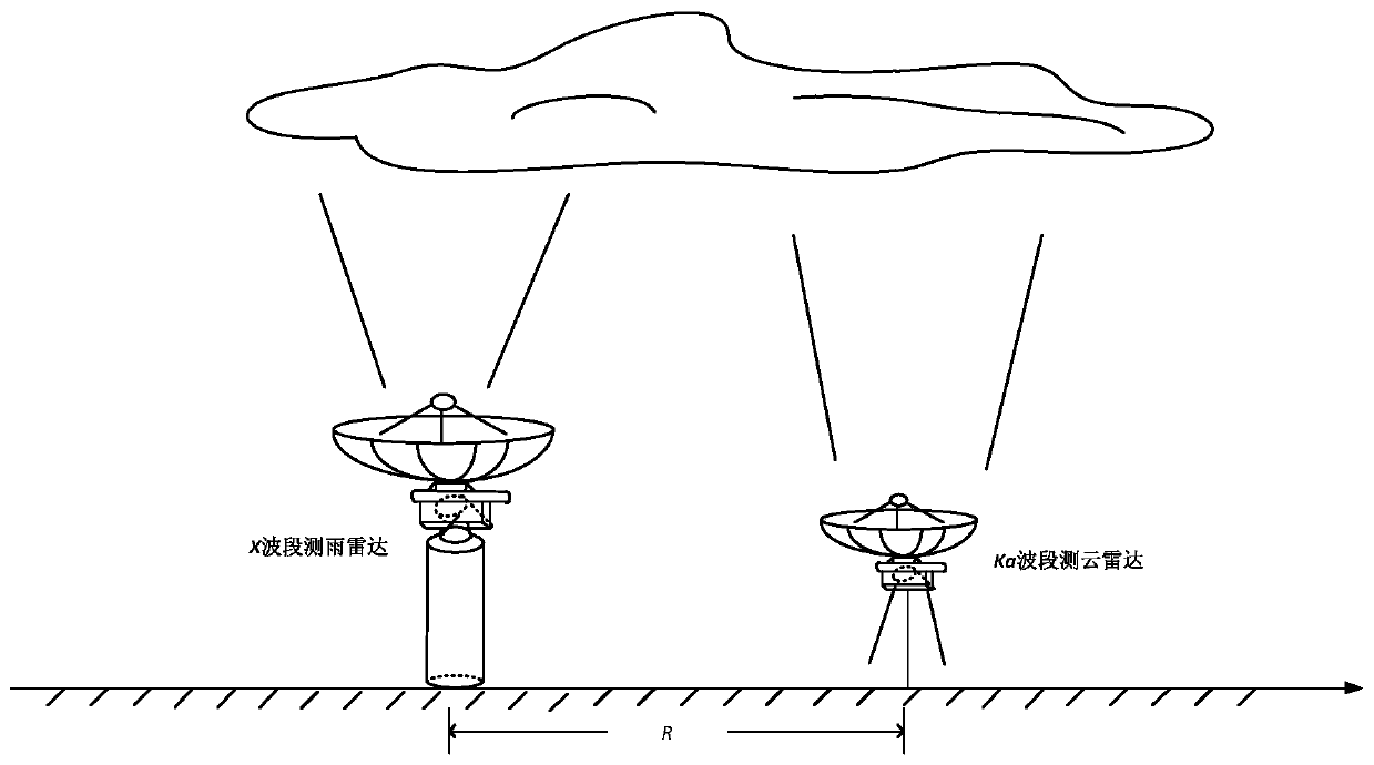
[0048] S11. Make the distance R between the X-band rain measuring radar and the Ka-band cloud measuring radar satisfy R∈[10,70]. In S11, the distance between the two radars is 10m-70m during observation. In actual observation, the separation distance can be adjusted according to the actual situation, and the adjustment needs to be satisfied: the two radars do not interfere with each other, and it is ensured that the two radars observe the same airspace.
[0049] Meteorological radar is one of the main detection tools for small and medium-scale strong convective weather. The purpose of using dual-band weather radar is to capture the evolution of the weather. The monitoring system takes into account the Ka-band and X-band to measure meteorological targets such as clouds and rain. The advantages of the above, using the scattering effect of clouds and precipitation on electromagnetic waves, quantitative detection of parameters such as the spatial position and distribution of clouds and rain, echo intensity, radial velocity, and velocity spectrum width within the range of action, can obtain the shape of the target , Phase state and spatial orientation, with high sensitivity, high spatial resolution, and high reliability.
[0050] Since cloud droplets are much smaller than precipitation particles, and the ability of cloud droplets to backscatter electromagnetic waves is proportional to the 6th power of the diameter of the cloud droplet and inversely proportional to the 4th power of the radar wavelength, the cloud measurement radar The wavelength is relatively short. The Ka-band has good scattering characteristics for targets with smaller diameters such as clouds and fog. The wavelength is closer to the scale of small particles and is more suitable for detecting weak clouds. The Ka-band can be used to detect unformed precipitation. The X-band rain measurement radar is more sensitive to raindrop particles with a diameter greater than a few hundred microns. These particles are the main components of storms and precipitation. The X-band rain measurement radar can be used To measure the echo intensity of precipitation clouds and strong convective weather, it can be used to calculate precipitation intensity and precipitation. When the two radars are working at the same time, consider making the X-band rain-measuring radar and the Ka-band cloud-measuring radar not less than the minimum detection distance of the radar, which can effectively avoid crosstalk between electromagnetic waves and enable the radar to effectively observe the target range.
[0051] S12. Set the X-band rain-measuring radar and Ka-band cloud-measuring radar to the vertical headspace continuous observation mode for synchronous detection to obtain the first echo data and the second echo data, as shown in figure 2 Shown.
[0052] In order to adapt to changes in weather and effectively capture the weather conditions, the weather radar has set a variety of scanning methods. The RHI (Elevation Scan) method is fixed in the specified direction, which is the working method for the radar to achieve profile analysis in the specified detection area; PPI The scanning method is a beam plane scanning method, that is, the radar is fixed at a certain angle and azimuth in the elevation, and the azimuth scanning range is unlimited from 0° to 360°, and the elevation can be fixed at any angle between 0° and 180° ; VOL (stereo scan) method is composed of multiple PPI scanning methods at different heights to work. This scanning method is very useful for analyzing the distribution of clouds in the entire airspace; THI (fixed-point scanning) is emitted by radar The beam keeps its azimuth and pitch position unchanged and faces a fixed point scanning method. This scanning method can emit more pulses for coherent or incoherent accumulation to improve the sensitivity of the radar system to detect weather targets with weaker echoes. Ka-band cloud radar and X-band rain radar are in vertical headspace continuous observation mode, which is THI scanning. figure 2 Schematic diagram of the joint detection of Ka and X-band rain measuring radar.
[0053] S2, extracting the second reflectivity factor of the second echo data obtained by the Ka-band cloud measuring radar and the first reflectivity factor of the first echo data obtained by the X-band rain measuring radar.
[0054] It specifically includes the following steps:
[0055] S21. Extract the reflectivity factor radial data of the second echo data of the Ka-band cloud survey radar, and set the coordinate axis according to the horizontal axis as the time (sampling time) and the vertical axis as the distance (the distance between the sampling point and the cloud survey radar) Way to get the matrix Z Ka.
[0056] For Ka-band weather radar, the observation area in the vertical headspace observation mode is S 1 ={(r p ,t)|r p ∈[0,30]; p=1,2,...,P}, where r p Is the distance between the sampling point on the observation area and the Ka-band cloud-measuring radar, t is the time (sampling time) of data collected by the Ka-band cloud-measuring radar. A set of echo data of the Ka-band weather radar is composed of P distance coordinates and t time A matrix Z consisting of P×Q sampling points composed of the radial data of the Q standard strips Ka , Matrix Z Ka Each column represents a radial data of the radar, and the data matrix Z Ka It is stored as shown below:
[0057]
[0058] Where each element of the matrix Z PQ Represents the intensity (unit: dBZ) of the reflectance factor of each grid point (sampling point P under the sampling time Q), matrix Z Ka Each column in it is a piece of radial data of the observation area of the Ka-band cloud-measuring radar, and the distance range is M∈[0,30] (unit: km).
[0059] S22. Extract the reflectivity factor radial data of the X-band rain measuring radar, and arrange the coordinate axis in such a way that the horizontal axis is time (sampling time) and the vertical axis is distance (distance between the sampling point and the rain measuring radar) to obtain a matrix Z X.
[0060] For the X-band rain measurement radar, its observation area in the vertical headspace observation mode is S 2 ={(r i ,t)|r i ∈[0,50]; i=1, 2,...,N}, where r i Is the distance between the sampling point in the observation area and the X-band rain measurement radar, t is the time when the X-band rain measurement radar collects data, and a set of echo data of the X-band rain measurement radar is transmitted by N distance coordinates and within t A matrix Z composed of Q radial data containing N×Q sampling points X , Matrix Z X Each column represents a radial data of the radar, and the data matrix Z X It is stored as shown below:
[0061]
[0062] Where each element of the matrix Z NQ Indicates the intensity of the reflectance factor (unit: dBZ) of each grid point (sampling point N at the sampling time Q), and the range of the X-band rain radar observation area N ∈ [0,50] (unit: km ).
[0063] S3. Fusion of the first reflectivity factor and the second reflectivity factor of each sampling point at each sampling time within the vertical headspace range of the first radar and the second radar extracted. Specific steps include:
[0064] S31. The extracted first reflectivity factor of each sampling point at each sampling time within the vertical headspace range of the first radar and the second reflection of each sampling point at each sampling time within the vertical headspace range of the second radar Rate factor for preprocessing.
[0065] The Ka-band cloud-measuring radar (second radar) has a shorter working wavelength and a higher emission frequency, and has a greater attenuation to the observation target. Its effective observation range is about 30km. The minimum detectable signal to the meteorological target is -40dBZ. The cloud observation effect is better. The grid with the median value of the Ka-band cloud-measuring radar reflectivity factor data below -40dBZ is assigned as null. The X-band rain-measuring radar has a relatively long working wavelength and low emission frequency, which will attenuate the observation target The effective observation range is within 50km, and the minimum detectable signal for meteorological targets is -15dBZ. It has a good observation effect on large-scale precipitation and hail and snowstorms. The X-band rain measurement radar reflectivity factor data Grids with a median value below -15dBZ are assigned null.
[0066] S32. Perform weight distribution on the reflectance factor data in the vertical headspace range measured by the first radar and the second radar by using a fuzzy logic method. The details are as follows:
[0067] Fuzzy logic was first proposed by the American mathematician L.Zadeh in 1965. Fuzzy logic is good at expressing problems with unclear boundaries. It uses the concept of membership function to distinguish fuzzy sets, process fuzzy relations, and simulate human brain rules to implement reasoning and solve the problem. Uncertain problems with unclear scope boundaries, fuzzy logic imitates the way of thinking of the human brain’s uncertainty concept. For description systems whose models are unknown or uncertain, fuzzy sets and fuzzy rules are used for reasoning to express transitional boundaries and implement fuzzy Comprehensive judgment.
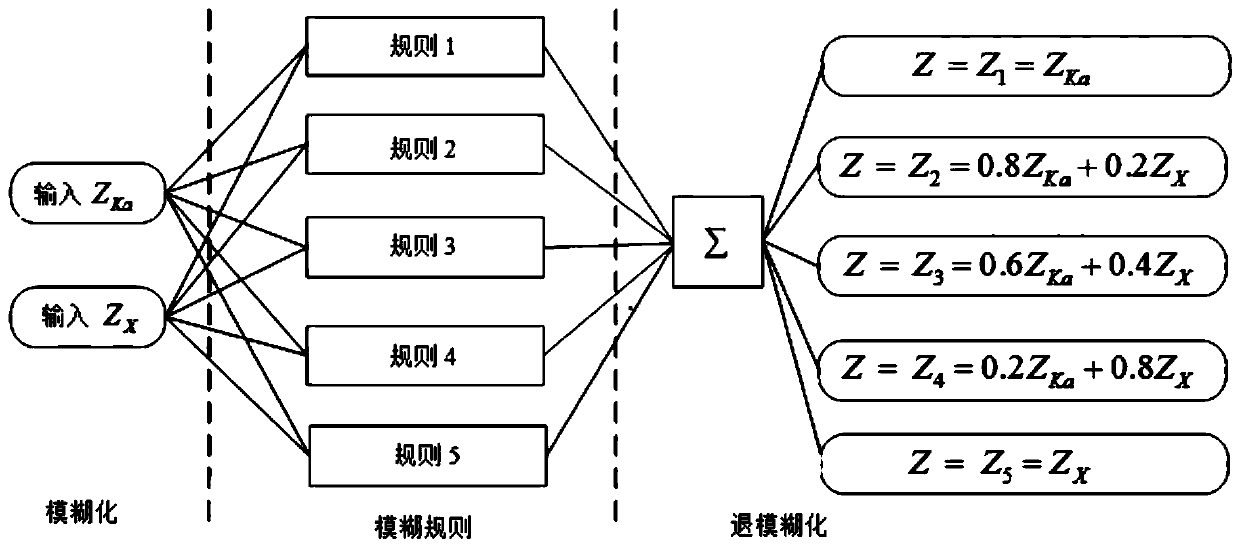
[0068] Construct a two-input five-output fuzzy logic system, and extract the reflectivity factor matrix Z of Ka-band cloud-measuring radar (second radar) and X-band rain-measuring radar (first radar) respectively Ka And Z X As the input of the system, inferring according to fuzzy rules, the output is Z Ka And Z X Are the weights of the reflectance factor intensity provided by the new matrix Z, image 3 Fuzzy logic algorithm framework diagram.
[0069] S321 Input variable fuzzification
[0070] Based on the first reflectance factor of each sampling point at each sampling time, use the preset first membership function corresponding to each category to calculate separately to obtain the first reflectance factor membership of each sampling point at each sampling time The first degree of membership in each category;
[0071] Based on the second reflectance factor of each sampling point at each sampling time, use the preset second membership function corresponding to each category to calculate separately, and obtain the second reflectance factor membership of each sampling point at each sampling time The second degree of membership in each category;
[0072] Perform calculation based on each first degree of membership of the first reflectance factor and each second degree of membership of the second reflectance factor of the same sampling point at the same sampling time to determine the category to which each sampling point at each sampling time belongs;
[0073] Determine the target reflectivity factor fusion formula according to the category to which each sampling point belongs at each sampling time;
[0074] The target reflectivity factor fusion formula corresponding to each sampling point at each sampling time is used to fuse the first reflectance factor and the second reflectivity factor of each sampling point at each sampling time to obtain the target reflectivity factor.
[0075] Take a specific situation as an example, as follows:
[0076] Five categories (Z1, Z2, Z3, Z4 and Z5) are preset, and each category corresponds to a target reflectance factor fusion formula (Z 1 ,Z 2 ,Z 3 ,Z 4 And Z 5 ). For each category, each input parameter can be calculated through the corresponding membership function (membership function 1. membership function 10) to obtain the membership degrees corresponding to the five categories. The membership function 1-membership function 10 can all adopt formula (4), and the interval of membership function 1-membership function 10 (that is, the values of a, b, c in formula (4)) is not The same, the specific is determined by referring to the interval marked in the fuzzy rule.
[0077] The following table illustrates the corresponding relationship between input parameters, category and degree of membership
[0078]
[0079] For the same pixel (the same sampling point at the same sampling time), after inputting the values of Ka and X, the fuzzy and fuzzy rules will be used to determine the degree of membership of each category f (it is a lot Probability value, namely FS in the following i ). Then use each f to calculate (formula (5)) to obtain output, and determine the category described by the emissivity factor of the sampling point at the sampling time according to the output value. For example, output=3, then the weight of this time Category output is Z 3 , Use Z when calculating 3 = 0.6Z Ka +0.4Z X This target reflectivity factor fusion formula integrates the first reflectivity factor and the second reflectivity factor to obtain the target reflectivity factor.
[0080] In this embodiment, each category is assigned a weight value in advance, the specific weight value of Z1 is 1, the weight value of Z2 is 2, the weight value of Z3 is 3, the weight value of Z4 is 4, and the weight value of Z5 is 5. , And the target reflectivity factor fusion formula is also preset, namely Z 1 =Z Ka;Z 2 = 0.8Z Ka +0.2Z X;Z 3 = 0.6Z Ka +0.4Z X;Z 4 =0.2Z Ka +0.8Z X;Z 5 =Z X.
[0081] That is, the reflectivity factor Z of each pixel in the two reflectivity factor matrix Ka And Z X As the input of the fuzzy logic system, for each input, the gradient of the pixel is mapped to the range of 0-1 using the preset triangular membership function (4), which means that the gradient belongs to Z Ka And Z X The degree of membership function is expressed as:
[0082]
[0083] Use the triangular membership function to define the degree to which the grid points belong to each category, where f represents the degree of membership, and x represents the input parameter (ie Z Ka And Z X ); The parameters a and c represent the foot points of the triangle, b represents the vertex of the triangle, and a, b, and c are the critical values of the reflectivity factor respectively, which can be set according to actual needs.
[0084] In this step, fuzzy rules can also be defined in the process of specific embodiments. The weights of the first reflectance factor and the second reflectance factor of each sampling point at each sampling time are directly obtained according to a preset fuzzy rule. Or use fuzzy rules to determine the critical values of a, b, and c in the membership function to determine the specific membership function.
[0085] The minimum detectable signal of the Ka-band cloud radar is -40dBZ and will produce greater attenuation when the precipitation echo is strong. The minimum detectable signal of the X-band precipitation radar is -15dBZ, which is suitable for monitoring strong precipitation echo. For monitoring in the same weather process, Ka-band cloud radar can detect some echoes that cannot be monitored by X-band rain-measuring radar. X-band rain-measuring radar has higher monitoring accuracy when heavy precipitation occurs. The purpose of setting fuzzy rules is to Ka And Z X The reflectance factors at the same target in the matrix are merged, and more accurate reflectance factor data is obtained when the matrices are merged.
[0086] Such as image 3 As shown, the specific fuzzy rules are as follows:
[0087] Rule 1: If -40dBZ≤Z Ka ≤-15dBZ is judged as Z1 type, and Z=Z is used in calculation Ka;
[0088] Rule 2: If -15dBZ Ka ≤15dBZ and -10dBZ X ≤15dBZ is judged as Z2 category, and Z=0.8Z is used in calculation Ka +0.2Z X;
[0089] Rule 3: If 10dBZ Ka <30dBZ and 10dBZ X <30dBZ is judged as Z3 category, and Z=0.6Z is used in calculation Ka +0.4Z X;
[0090] Rule 4: If 25dBZ≤Z Ka ≤60dBZ and 25dBZ≤Z X ≤60dBZ is judged as Z4 category, and Z=0.2Z is used in calculation Ka +0.8Z X;
[0091] Rule 5: If 55dBZ≤Z Ka And 60dBZ≤Z X Or r i When ∈(30,50), it is judged as Z5 type, and Z=Z is used in calculation X.
[0092] Among them, Z represents the target reflectivity factor.
[0093] S323 fuzzy reasoning
[0094] Through the recombination of fuzzy rules and fuzzy logic operations, for the preconditions of each rule, the membership degree FS of the input data is calculated i (I.e. f), based on the value given in the rule to determine the determined result of the calculation of this rule, integrate all the inference conclusions into a single conclusion, and put it into a fuzzy set. Take a grid point as an example: Z of the same sampling point at the same sampling time ka =20dBZ and Z X =20dBZ, use this as input to calculate the membership degree of the grid point belonging to each category, and each grid point has a corresponding membership degree FS i.
[0095] In this embodiment, the membership degree FS of each grid point is obtained i After that, the de-blurring can be performed.
[0096] Fuzzy logic transforms the input matrix value into the membership degree FS of each set through fuzzification i After that, several fuzzy inference values are obtained through fuzzy rules and operations. The fuzzy inference values need to be de-fuzzified by the weighted average decision method to obtain the output value. The output is:
[0097]
[0098] Among them, FS i For the output of the previous step, ow (output wight) is the weight, and the weight is the intermediate value of each fuzzy set. The output corresponding to each sampling point at each sampling time is obtained by calculation, and the values corresponding to each output and each category are calculated Compare to determine the category of each sampling point at each sampling time.
[0099] S33. Set the reflectivity factor matrix Z in the vertical headspace range of the Ka-band cloud measurement radar Ka The reflectivity factor matrix Z in the vertical headspace range of the Ka-band cloud measurement radar X Overlay, multiply the intensity value by the weight at each grid to obtain the joint reflectivity factor matrix (ie, the target reflectivity factor matrix) Z in the vertical headspace range, and the matrix Z contains N×Q sampling points.
[0100] S4. Calculate the liquid water content in the cloud within the detection range using radar data according to the Z-M (reflectance factor-liquid water content) relationship.
[0101] In the specific embodiment of this step, the integral form Z of the known radar reflectivity factor is:
[0102]
[0103] Among them, D is the raindrop diameter, N 0 And k are the parameters when the raindrop spectrum in the precipitation cloud conforms to the M-P distribution, and the corresponding cloud water content M is:
[0104]
[0105] From formulas (6)(7), the Z-M relationship can be obtained:
[0106] M=3.44×10 -3 ×Z 4/7 (8)
[0107] Equation (8) can be directly used for calculation.
[0108] S41. Bring the joint reflectance factor matrix Z in the vertical headspace range into the Z-M relationship to calculate the liquid water content M in the cloud within the detection range.
[0109] Put the combined reflectivity factor grid point value Z into the above formula to obtain the liquid water content M in the cloud within the detection range.
[0110] S5. Calculate the cloud thickness within the detection range.
[0111] S51. Calculate the cloud base height H using the joint reflectivity factor matrix Z in the vertical headspace range base And cloud top height H top.
[0112] In THI mode, the reflectance factor data is that each ray is arranged in column order. The matrix Z contains N×Q sampling points. Read the distance library length represented by each grid in the matrix Z, starting from the approach to the radar antenna direction. Read all non-empty grid point coordinates P i (i=1,2,3,4,...N), P i The maximum coordinate multiplied by the distance library length is the cloud top height H top , P i The minimum coordinate multiplied by the distance library length is the cloud base height H base.
[0113] S52, use H top -H base Calculate the cloud thickness Depth obtained by radar joint detection.
[0114] S6. Calculate the vertical cumulative liquid water content within the vertical headspace of the radar.
[0115] The VIL product reflects the total liquid water content of the precipitation cloud in a vertical cylinder with a certain bottom area. When calculating the VIL, it is first assumed that all reflectivity factors in the cloud are formed by liquid water, and then based on the droplet spectrum distribution theory and the above The ZM relationship of the formula is derived. VIL mainly describes how to convert the weather radar reflectivity factor into the accumulated liquid water content in the cloud. VIL is the total water content of the cloud in a vertical cylinder with a certain bottom area. The integral of the liquid water content M in the cloud from the bottom to the cloud top height can be expressed as:
[0116]
[0117] S61. Integrate M under the cloud thickness Depth to obtain the vertical cumulative liquid water content VIL that is jointly detected by the Ka-band cloud-measuring radar and the X-band rain-measuring radar in the vertical headspace range.
[0118] Take the cloud base height H represented by the matrix Z obtained in the previous step base And cloud top height H top And the water content in the cloud M obtained by the inversion is brought into the above formula, and the vertical cumulative liquid water content VIL obtained by the joint detection of the Ka and X dual-band weather radar is calculated.
[0119] The inversion method of radar vertical accumulated liquid water content of the present invention has the following beneficial effects:
[0120] (1) The present invention can calculate the vertical cumulative liquid water content in the vertical headspace range of the radar in real time based on weather radar data, and improve the accuracy of forecasting strong weather processes.
[0121] (2) The present invention uses the Ka-band cloud-measuring radar and the X-band rain-measuring radar to work together in a vertical headspace detection mode. The discrete summation process of the body scan data is omitted in the calculation, which improves the inversion accuracy of the vertical cumulative liquid water. The calculation method is simple, which speeds up the calculation and improves the efficiency of the calculation.
[0122] The above embodiments are only exemplary embodiments of the present invention and are not used to limit the present invention. The protection scope of the present invention is defined by the claims. Those skilled in the art can make various modifications or equivalent substitutions to the present invention within the essence and protection scope of the present invention, and such modifications or equivalent substitutions should also be regarded as falling within the protection scope of the present invention.
PUM


Description & Claims & Application Information
We can also present the details of the Description, Claims and Application information to help users get a comprehensive understanding of the technical details of the patent, such as background art, summary of invention, brief description of drawings, description of embodiments, and other original content. On the other hand, users can also determine the specific scope of protection of the technology through the list of claims; as well as understand the changes in the life cycle of the technology with the presentation of the patent timeline. Login to view more.
Similar technology patents
Techniques for sentiment analysis of data using a convolutional neural network and a co-occurrence network
Owner:ORACLE INT CORP
Adaptive fault detection method for airplane rotation actuator driving device based on deep learning
Owner:BEIHANG UNIV
Portable reference station for local differential GPS corrections
Owner:HEMISPHERE GNSS
Automatic or semi-automatic cooking equipment and batch charging mechanism thereof
Owner:AIC ROBOTICS TECH
Communication terminal apparatus and communication system
Owner:SONY ERICSSON MOBILE COMM JAPAN INC
Classification and recommendation of technical efficacy words
- improve accuracy
Golf club head with adjustable vibration-absorbing capacity
Owner:FUSHENG IND CO LTD
Stent delivery system with securement and deployment accuracy
Owner:BOSTON SCI SCIMED INC
Method for improving an HS-DSCH transport format allocation
Owner:NOKIA SOLUTIONS & NETWORKS OY
Catheter systems
Owner:ST JUDE MEDICAL ATRIAL FIBRILLATION DIV
Gaming Machine And Gaming System Using Chips
Owner:UNIVERSAL ENTERTAINMENT CORP