
Target tracking system, method and device based on GPS and dome camera

A target tracking and ball camera technology, which is applied in the field of GPS-based target tracking systems, and can solve the problems of small monitoring target tracking range and limited camera monitoring range.

Pending Publication Date: 2020-06-16
HANGZHOU HIKVISION DIGITAL TECH
View PDF6 Cites 10 Cited by
  • Summary
  • Abstract
  • Description
  • Claims
  • Application Information

AI Technical Summary

Problems solved by technology

[0003] However, the monitoring range of a camera is limited. In the above scheme, if the monitoring target moves out of the monitoring range of the camera, the tracking of the monitoring target will stop.
It can be seen that this scheme has a small tracking range for monitoring targets

Method used


Image

  • Target tracking system, method and device based on GPS and dome camera
  • Target tracking system, method and device based on GPS and dome camera
  • Target tracking system, method and device based on GPS and dome camera

Examples


Embodiment approach

[0234] As an implementation manner, the device further includes: a receiving module, a second determining module, and an adjusting module (not shown in the figure), wherein,

[0235] A receiving module, configured to receive the GPS coordinates of the target to be tracked sent by the server or a camera other than the first camera;

[0236] The second determination module is configured to determine the PT coordinates when the first camera shoots the target to be tracked according to the received GPS coordinates of the target to be tracked;

[0237] An adjustment module, configured to adjust the shooting angle of the first camera based on the PT coordinates.

[0238] As an implementation manner, the second determining module is specifically used for:

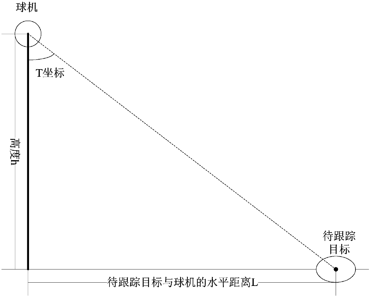
[0239] According to the GPS coordinates of the target to be tracked and the GPS coordinates of the first camera photographing the target to be tracked, calculate the distance in the meridian direction and the distance in the lati...


PUM


Abstract

The embodiment of the invention provides a target tracking system, method and device based on a GPS and a dome camera. The system comprises a first camera and a second camera. The first camera obtainsGPS coordinates of the target in the process of tracking the target, and sends the GPS coordinates to the second camera; and the second camera adjusts the shooting angle of the second camera according to the GPS coordinates, and controls itself to track the target after detecting the target in a second monitoring image shot by the second camera. Visibly, in the scheme, if the target moves out ofthe monitoring range of the first camera, the second camera continues to track the target, i.e., the tracking range of the target is improved through the linkage of the plurality of cameras.

Description

technical field [0001] The invention relates to the field of security technology, in particular to a GPS-based target tracking system, method, device and ball machine. Background technique [0002] In some scenarios, monitoring objects such as vehicles and people can be tracked through monitoring images captured by cameras. The tracking scheme may include: detecting the monitoring target to be tracked in the Nth frame of image, determining the position of the monitoring target in the N+1th frame of image and subsequent images through the target tracking algorithm, and converting the position into GPS coordinates. In this way, the GPS coordinates of the monitoring target can be obtained continuously, and the tracking of the monitoring target is realized. [0003] However, the monitoring range of a camera is limited. In the above solution, if the monitoring target moves out of the monitoring range of the camera, the tracking of the monitoring target stops. It can be seen tha...

Claims


Application Information

Patent Timeline
IPC IPC(8): G06K9/00H04N7/18
CPCH04N7/181G06V20/42G06V2201/07G06V20/52G01S19/485H04N7/18G06T7/292G06T2207/30232H04N23/69
Inventor 李勇金海善王威
Owner HANGZHOU HIKVISION DIGITAL TECH
Learn More