
Fast lock-in all-digital phase-locked loop with extended tracking range

a phase-locked loop and all-digital technology, applied in the field of phase-locked loops, can solve the problem of insensitive lock-in time to the bandwidth of the loop, and achieve the effect of extending the tracking range and reducing the time of lock-in

Active Publication Date: 2011-08-09
REALTEK SEMICON CORP
View PDF14 Cites 3 Cited by
  • Summary
  • Abstract
  • Description
  • Claims
  • Application Information

AI Technical Summary

Benefits of technology

The present invention provides an apparatus and method to reduce the lock-in time of an all-digital phase-locked loop (ADPLL) by using a digitally controlled oscillator (DCO) with a tuning circuit. The invention also includes a method to extend the tracking range of the ADPLL over voltage and temperature variations by enabling and disabling tuning circuit elements based on the number of rising edges of a first clock in a number of second clock cycles. The invention further provides a fast lock-in process by aligning the rising edges of a third and fourth clock and using a bang-bang phase detector to adjust the oscillation frequency of the DCO. The invention can maintain lock by detecting lead and lag phase relationships between the clocks and adjusting the tuning circuit elements accordingly. The technical effects of the invention include reducing the lock-in time of the ADPLL and improving its tracking performance over voltage and temperature variations.

Problems solved by technology

The resultant lock-in time is rather insensitive to the loop bandwidth.

Method used


Image

  • Fast lock-in all-digital phase-locked loop with extended tracking range
  • Fast lock-in all-digital phase-locked loop with extended tracking range
  • Fast lock-in all-digital phase-locked loop with extended tracking range

Examples


Embodiment Construction

[0031]In the present disclosure, numerous specific details are provided, such as examples of electrical circuits, components, and methods, to provide a thorough understanding of embodiments of the invention. Persons of ordinary skill in the art will recognize, however, that the invention can be practiced without one or more of the specific details. In other instances, well-known details are not shown or described to avoid obscuring aspects of the invention.

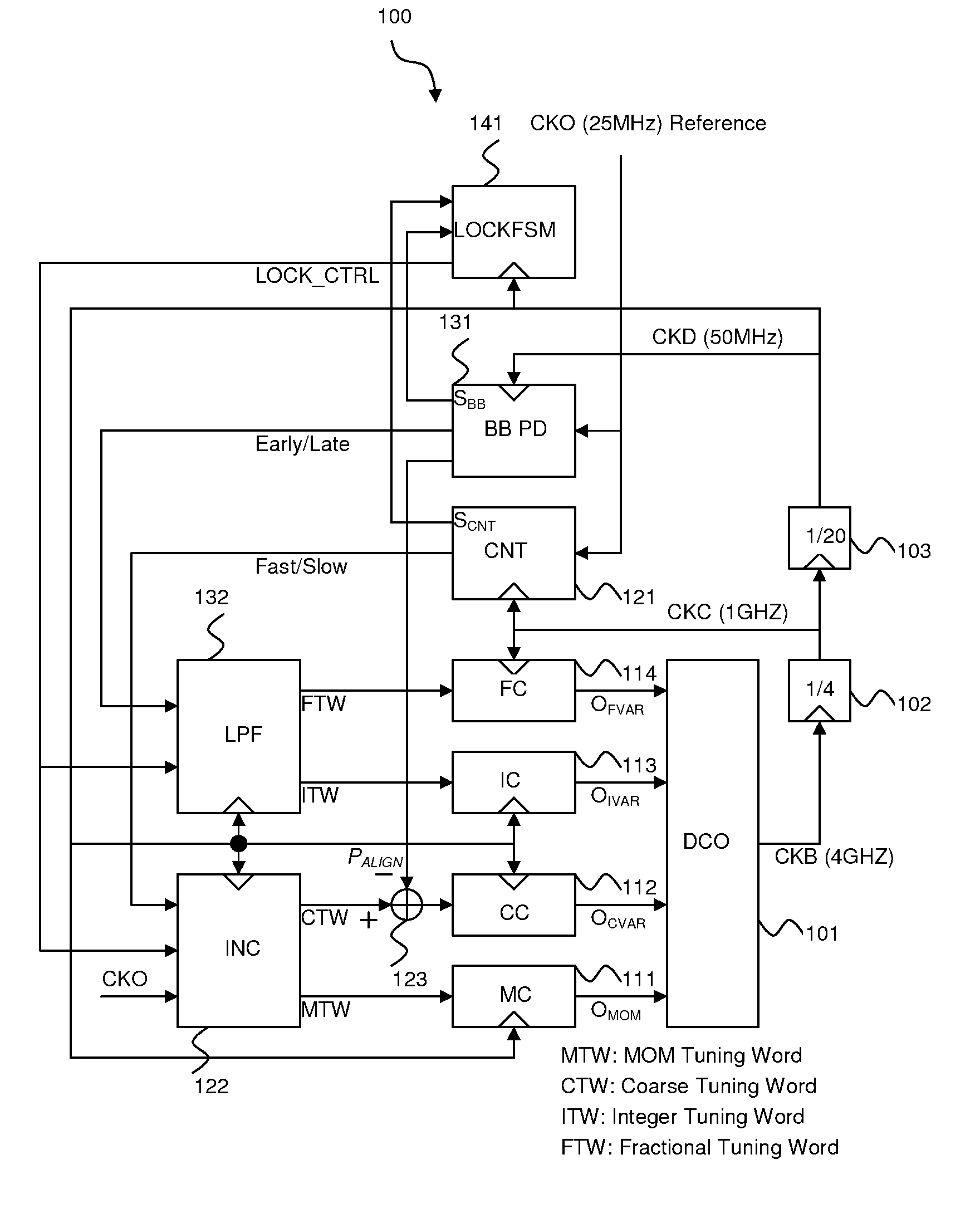
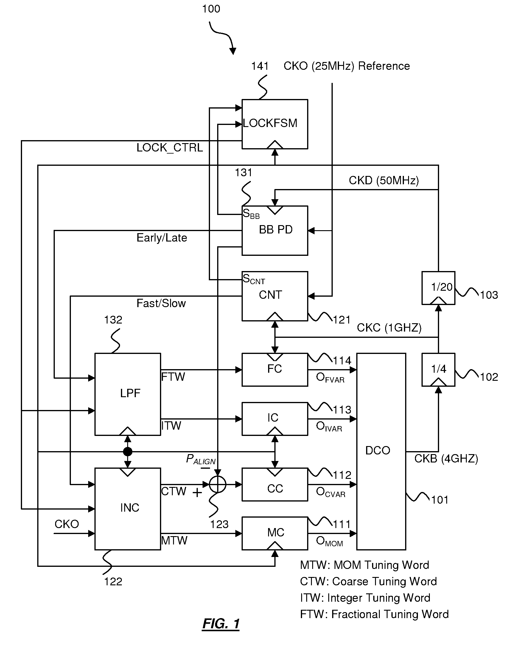
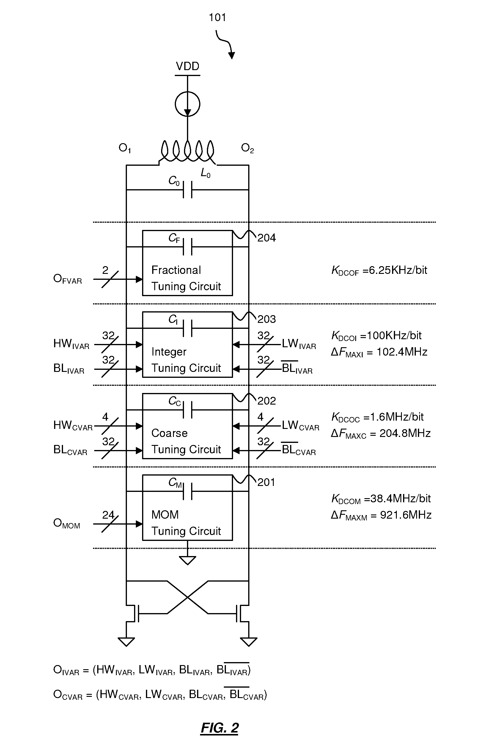
[0032]Embodiments of the present invention advantageously allow for fabrication of an all-digital controlled phase-locked loop. FIG. 1 shows an all-digital phase-locked loop in accordance with an embodiment of the present invention. The all-digital phase-locked loop comprises a digitally controlled oscillator (DCO) 101, a divide-by-N frequency divider 102 (for example, N=4), a divide-by-M frequency divider 103, a MOM controller (MC) 111, a coarse controller (CC) 112, an integer controller (IC) 113, a fractional controller (FC) 114...


PUM


Abstract

An apparatus and a method for achieving lock-in of a phase-locked loop (PLL) are disclosed. The PLL receives a reference clock and generates an output clock according to the reference clock. The method comprises: adjusting an oscillation frequency of a controlled oscillator of the PLL close to a desired frequency by counting the number of rising edges of a first clock in a number of a second clock cycles; aligning a rising edge of a third clock and a rising edge of a fourth clock by temporarily changing the oscillation frequency of the digitally controlled oscillator; and locking the phases of the third and fourth clocks by a phase detector of the PLL, wherein the first and the third clocks correspond to the output clock and the second and fourth clocks correspond to the reference clock.

Description

BACKGROUND OF THE INVENTION[0001]1. Field of the Invention[0002]The present invention relates generally to a phase-locked loop (PLL), and more particularly to a fast lock-in phase-locked loop.[0003]2. Description of the Background Art[0004]Deep-submicron technology favors digitally intensive designs due to its smallfeature sizes, low supply voltages, large gate leakage currents, etc. The small feature size significantly reduces the area cost of a digital circuit whereas the area of an analog circuit generally does not scale well with the feature size. The low supply voltage limits the headroom of an analog circuit whereas a digital circuit has better noise immunity than the analog counterpart due to its binary operation nature. Even more, the jitter of an analog phase-locked loop (PLL) is usually subjected to leakage currents in a monolithic sub-micron low pass filter. In contrast, a digital low pass filter can completely eliminate this problem to improve the jitter performance.[000...

Claims


Application Information

Patent Timeline
Patent Type & Authority Patents(United States)
IPC IPC(8): H03L7/06
CPCH03L7/091H03L7/113H03L7/099H03L2207/50
Inventor HSIEH, HONG-YEANLEE, CHAO-CHENG
Owner REALTEK SEMICON CORP
Learn More