[0047] The present invention will be further described below in conjunction with the drawings and embodiments. The present invention includes but is not limited to the following embodiments.
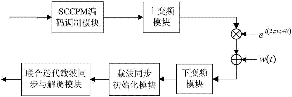
[0048] The invention can be applied in the fields of telemetry communication, satellite communication, military communication, etc., by using the second-order PLL structure to realize carrier synchronization, and by means of the iterative demodulation algorithm in the SCCPM system to realize data demodulation and ensure the reliability of communication.
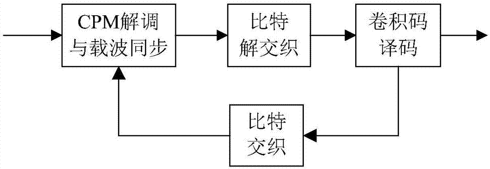
[0049] The idea of the method of the present invention is: first use the carrier synchronization initialization module to obtain the initial carrier estimation information and CPM bit logarithmic input probability for iterative, and then use the joint iterative carrier synchronization and demodulation module to perform carrier tracking and iterative demodulation to achieve accuracy The carrier synchronization and reliable signal demodulation.
[0050] Reference figure 1 The system of the present invention includes 5 modules: SCCPM coding and modulation module, up-conversion module, down-conversion module, carrier synchronization initialization module and joint iteration carrier synchronization and demodulation module. Among them, the carrier synchronization initialization module and the joint iteration carrier synchronization and demodulation module belong to the unique modules of the present invention.
[0051] The SCCPM encoding and modulation module is used to encode and modulate the source information bits received by the SCCPM encoding and modulation module into an SCCPM baseband signal waveform;
[0052] The up-conversion module is used to convert the baseband signal waveform received by the up-conversion module into a frequency band signal waveform through spectrum shifting;
[0053] The down-conversion module is used to convert the frequency band signal waveform contaminated by Doppler frequency offset and Gaussian white noise received by the down-conversion module into a baseband complex signal waveform through spectrum shifting;
[0054] The carrier synchronization initialization module is used to calculate the CPM bit logarithmic posterior probability and the modulation waveform logarithmic posterior probability according to the CPM state grid transfer structure using the Log-MAP demodulation algorithm. Probability and carrier phase estimation values, which are respectively used as initialization bits of CPM to input log probability, initialized modulation waveform logarithmic output probability and initialized carrier phase value to the joint iterative carrier synchronization and demodulation module;
[0055] The joint iterative carrier synchronization and demodulation module is used to embed the second-order PLL into the CPM demodulation algorithm, and realize the iterative demodulation and carrier synchronization between the CPM and the convolutional code through the Log-MAP algorithm.
[0056] Reference figure 2 versus Figure 4 The steps of the joint iterative carrier synchronization and demodulation module of the present invention are as follows:
[0057] (1) Code modulation:
[0058] The source information bits are encoded and modulated to obtain the SCCPM baseband signal waveform, which is sent to the up-conversion module;
[0059] (2) Up-conversion:
[0060] Convert the frequency band signal waveform received by up-conversion into frequency band signal waveform through spectrum shift;
[0061] (3) Channel noise:
[0062] Transmit the frequency band signal waveform obtained by upconversion to the downconversion module through the additional carrier frequency offset and phase offset Gaussian white noise channel;
[0063] (4) Down conversion:
[0064] Convert the frequency band signal waveform contaminated by Doppler frequency deviation and Gaussian white noise received by the down-conversion module into a baseband complex signal waveform through spectrum shifting, and transmit it to the carrier synchronization initialization module;
[0065] (5) Initial parameter calculation:
[0066] (5.1) According to the state grid transfer structure of CPM, the Log-MAP algorithm is used to calculate the forward state logarithmic probability correction value α of CPM at each time when the carrier parameter value is included. k (s)(k=0,1,...,N) and the estimated value of the forward carrier phase Where N is the number of CPM symbols.
[0067] Forward carrier phase estimate The iterative calculation method is as follows:
[0068]
[0069] Among them, the initial value Carrier error correction for forward The results obtained by modifying the loop filter of the second-order PLL, please refer to the attached image 3. Forward corrected carrier error The calculation method is as follows:
[0070]
[0071] Among them, Im{·} is the imaginary part operation of the complex baseband signal; S n Is the possible modulation waveform of CPM, z k (S n ) Is the received signal vs. waveform S n Demodulation operation:
[0072]
[0073] ψ(S n ) Is the CPM waveform is S n The corresponding complex baseband phase expression at time. Is the carrier phase is Time waveform S n The forward modified posterior probability of is calculated as follows:
[0074]
[0075] Among them, refer to Figure 4 Schematic diagram of the state transition grid in the CPM state, e is the edge in the state transition graph in the CPM state grid structure, Is the starting state of edge e, Is the end state of side e, u(e) is the input symbol corresponding to side e, and S(e) is the output waveform corresponding to side e. a k (s) is the probability correction value when the current state of the forward state transition structure is s when using the Log-MAP algorithm to demodulate the CPM. The calculation method is as follows:
[0076] a k (s)=exp(α k (s))
[0077] Define operation
[0078] max * (x,y)=ln(exp(x)+exp(y))
[0079] Then when the carrier parameter value is included, the CPM forward state log probability correction value α k (s)(k=0,1,...,N) The calculation method is as follows:
[0080]
[0081] (5.2) According to the state grid transfer structure of CPM, the Log-MAP algorithm is used to calculate the backward state logarithmic probability correction value β of CPM at each time when the carrier parameter value is included. k (s)(k=0,1,...,N) and the estimated value of the backward carrier phase
[0082] Backward carrier phase estimate The iterative calculation method is as follows:
[0083]
[0084] among them, Carrier error correction for backward The result obtained by modifying the loop filter of the second-order PLL. Backward corrected carrier error The calculation method is as follows:
[0085]
[0086] among them, Is the carrier phase is Time waveform S n The backward modified posterior probability of is calculated as follows:
[0087]
[0088] b k (s) represents the probability correction value when the current state is s in the backward state transition structure when using the Log-MAP algorithm to demodulate the CPM. The calculation method is as follows:
[0089] b k (s)=exp(β k (s))
[0090] When the carrier parameter is included, the calculation method of the log probability correction value of the backward state is as follows:
[0091]
[0092] (5.3) According to the state grid transfer structure of CPM, the Log-MAP algorithm is used to calculate the symbol logarithm posterior probability of CPM when the carrier parameter value is included at each time. k (u; O) (k=1,2,...,N) and the logarithmic posterior probability of modulation waveform λ k (S;O)(k=1,2,...,N);
[0093]
[0094]
[0095] (5.4) Calculate the bit log posterior probability λ according to the symbol log posterior probability of CPM m (u j ,O)(j=1,2,...,log 2 M; m=1, 2,...,L). Among them, M is the symbol base number of CPM, L is the number of modulation bits of CPM, satisfying L=N×log 2 M.
[0096]
[0097] Among them, int[·] is the operation of rounding down.
[0098] (5.5) Calculate the carrier phase estimation value at each moment
[0099]
[0100] (5.6) Initialize the CPM bit logarithmic input probability of the joint iterative carrier synchronization and demodulation module as The logarithmic input probability of the CPM modulation waveform is initialized as The input carrier phase is initialized to The iteration index is initialized to i=1. According to the required bit error performance and implementation complexity, set the maximum number of iterations Q;
[0101] (6) Joint iterative carrier synchronization and demodulation:
[0102] (6.1) CPM demodulation and carrier estimation:
[0103] (6.1.1) According to the state grid transfer structure of CPM, the Log-MAP algorithm is used to calculate the logarithmic probability of the CPM forward state at each moment when the carrier parameter value is included. And according to the second-order PLL structure, use the input carrier phase value Calculate the forward carrier phase estimation value at each moment
[0104] Forward carrier phase estimate The calculation method is as follows:
[0105]
[0106] Among them, the initial value Forward carrier error The result obtained by the loop filter of the second-order PLL. Forward carrier error The calculation method is as follows:
[0107]
[0108] The logarithmic probability of the forward state of the CPM when the carrier parameter value is included The calculation method is as follows:
[0109]
[0110] among them, Is the log probability value of the input symbol when the symbol of the i-th iteration is u, which can be calculated from the log probability value of the input bit
[0111]
[0112] (6.1.2) According to the state grid transfer structure of CPM, the Log-MAP algorithm is used to calculate the logarithmic probability of the backward state of the CPM when the carrier parameter value is included at each time. And according to the second-order PLL structure, use the input carrier phase value Calculate the estimated value of the backward carrier phase at each moment
[0113] Backward carrier phase estimate The calculation method is as follows:
[0114]
[0115] among them, Is the backward carrier error The result obtained by the loop filter of the second-order PLL. Backward carrier error The calculation method is as follows:
[0116]
[0117] Log Probability of CPM Backward State with Carrier Parameter Value The calculation formula is
[0118]
[0119] (6.1.3) According to the state grid transition structure of CPM, the Log-MAP algorithm is used to calculate the logarithmic posterior probability of CPM when the carrier parameter value is included at each time. Logarithmic posterior probability of modulating waveform
[0120]
[0121]
[0122] (6.1.4) Calculate the bit log posterior probability according to the CPM symbol log posterior probability
[0123]
[0124]
[0125] (6.1.5) Calculate the output carrier phase value at each moment
[0126]
[0127] (6.2) Convolutional code decoding:
[0128] (6.2.1) The CPM bit logarithmic posterior probability minus the bit logarithmic input probability, after the bit deinterleaving module, is used as the input logarithmic probability of the convolutional code word bit Send to the convolutional code decoding module
[0129]
[0130] Among them, X represents the bit interleaver in SCCPM, X -1 Represents the bit deinterleaver corresponding to the interleaver.
[0131] (6.2.2) According to the state grid transition diagram of convolutional coding, use Log-MAP algorithm to calculate the logarithmic posterior probability of convolutional code information bits Logarithmic posterior probability of codeword with convolutional code Among them, K is the number of convolutional code information bits;
[0132] (6.3) Iterative update
[0133] Update the CPM bit logarithmic input probability in the next iteration to the posterior probability of the convolutional code codeword bit logarithm in the current iteration minus the output result of the convolutional code codeword bit logarithmic input probability after the bit interleaving module, namely
[0134]
[0135] Update the logarithmic input probability of the CPM waveform at the next iteration to the posterior probability of the CPM waveform at the current iteration minus the logarithmic input probability of the CPM waveform, that is
[0136]
[0137] Update the input carrier phase value in the next iteration to the output carrier phase value in the current iteration, namely
[0138]
[0139] Let i=i+1, repeat step (3.1), and start the next iteration;
[0140] (6.4) Judgment output:
[0141] When the number of iterations i reaches the set value Q, the source information bit is determined according to the logarithmic posterior probability of the convolutional code information bit.
[0142] Reference attached image 3 , The second-order PLL structure loop filter structure in the carrier synchronization of the present invention includes C 1 With C 2 The relationship between the two parameters and the noise bandwidth B is as follows:
[0143]
[0144]
[0145]
[0146] Among them, T is the symbol period of the CPM, K is the loop gain of the second-order PLL, and ξ is the damping factor of the second-order PLL. Generally, ξ=0.707 in engineering.
[0147] Combine below Figure 6 ~ Figure 10 The effect of the present invention will be further explained.
[0148] The simulation of the present invention uses Matlab2010 simulation software, and the simulation parameters are set as follows: In the SCCPM coding modulation module, the coding structure adopts a generator polynomial as g=(5,7) 8 Non-systematic convolutional code; CPM structure adopts a full response modulation method with a frequency pulse function of raised cosine pulse, a modulation index of h=1/2, and a base number of M=2; the channel model uses additional carrier frequency offset and phase offset Gaussian white noise channel; the data frame length of each frame is 1000 CPM symbols. The number of iterations of joint iterative carrier synchronization and demodulation is 4 times.
[0149] It is assumed that the carrier frequency offset v and the carrier phase offset θ added to the channel are uniformly distributed under vε(-0.01,0.01T)/and θε(-π,π) respectively. Under different signal-to-noise ratio conditions, the joint iterative carrier synchronization and demodulation algorithm of the present invention is used to test the influence of different normalized noise bandwidths on the BER performance of the SCCPM system.
[0150] From Figure 6 ~ Figure 9 It can be seen that the iterative carrier synchronization and demodulation algorithm of the present invention gradually decreases the BER curve as the number of iterations increases. However, from Picture 10 It can be seen that as the normalized noise bandwidth decreases, the BER performance of the system gradually approaches the BER performance under ideal carrier synchronization. This is because a larger normalized noise bandwidth will introduce more loop noise, and the tracking performance of the system will decrease. However, in actual engineering, a smaller normalized noise bandwidth will cause a longer capture time and a smaller tracking range. In engineering practice, the choice of noise bandwidth should be considered comprehensively based on various indicators.