Optical tracking device employing scanning beams on symmetric reference

US6854847B2Inactive Publication Date: 2005-02-15LAI MING +1

Image

  • Optical tracking device employing scanning beams on symmetric reference
  • Optical tracking device employing scanning beams on symmetric reference
  • Optical tracking device employing scanning beams on symmetric reference

Examples


Embodiment Construction

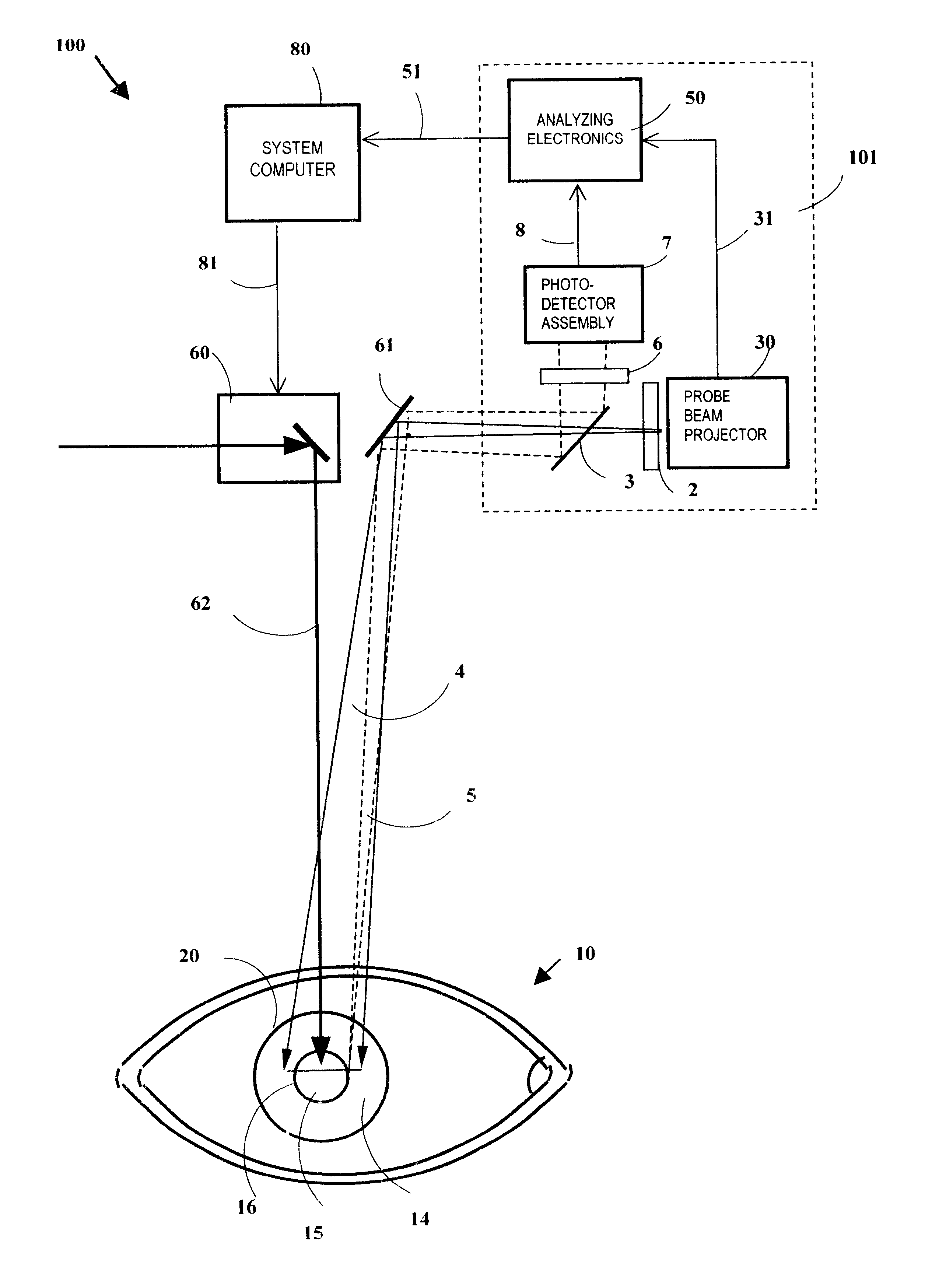
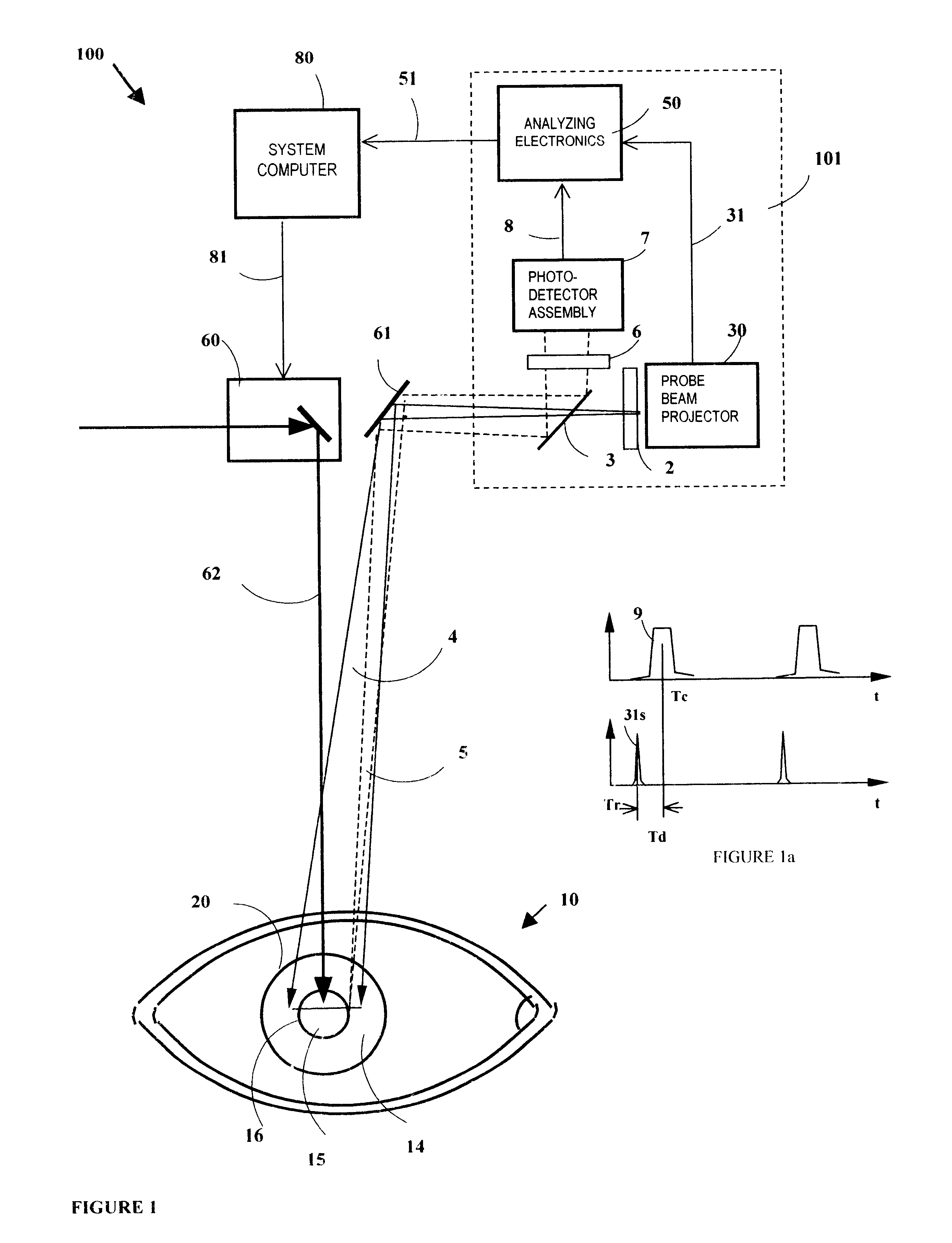
FIG. 1 is a schematic diagram of an optical tracking device 101 in an open loop configuration for a surgical laser beam delivery system 100, in accordance with on embodiment of the present invention. The beam delivery system 100 implements an open loop configuration that includes a tracking device 101, a system computer 80, a surgical laser beam 62, and a beam steering module 60 (e.g., a x-y scanner). The tracking device 101 projects a scanning probe beam 4 and monitors the position of the eye 10. Using the eye positioning data from the tracking device 101, the system computer 80 controls the beam steering module 60 to direct the surgical laser beam 62 to follow the eye movement and to impinge on predetermined position on the eye 10. As an open loop configuration, the scanning probe beam 4 does not follow the movement of the eye 10 and only one beam steering module 60 is required.

For illustration purpose, the tracking device 101 shown in FIG. 1 projects only a first probe beam 4 sca...


PUM


Abstract

The optical tracking device of the present invention is contemplated to obtain a large tracking range in an open loop configuration. The tracking device projects and scans two probe beams across a symmetric reference landmark that has at least two symmetric lines or axes. The two probe beams scan repeatedly and alternatively along two directions of which each is perpendicular to a symmetric line of the reference mark. For each scan, a substantially symmetric profile is generated in the scattered light as the beam scans across the boundary on each side of the symmetric reference. This symmetric profile in the scattered light is detected and used to determine the position of the related symmetric line. The position detection of the symmetric line is independent from the object's movement along the direction of the symmetric line. The scattered-light signal from the two probe beams is separated by synchronized detection in the time domain. This way, the two probe beams scan and sense the positions of two symmetric lines and then the crossing point between the two lines determines the lateral position of the object to be tracked. The two symmetric lines may or may not be perpendicular to each other. The range of this detection is substantially as large as the size of the reference landmark.

Description

TECHNICAL FIELDThe present invention relates to an optical tracking device that tracks the lateral displacement of an object that has a symmetric reference landmark with at least two symmetric axes. In particularly, the present invention relates to an optical tracking device that tracks the lateral displacement of a subject's eye during a laser refractive surgery.BACKGROUNDIn U.S. Pat. No. 6,179,422 to Lai, an optical tracking device is described to employ two scanning beams to scan across boundaries of a reference mark affixed on an object to be tracked. In an embodiment of eye tracking, the device projects two beams scanning across the limbus at 12 and 3 o'clock positions, respectively. The device detects the timing of the probe beam scanning across the limbus and thus determines the lateral position of the subject's eye.Two configurations have been described in U.S. Pat. No. 6,179,422 to implement the tracking device. The first one is of open loop, in which the scanning probe bea...

Claims


Application Information

Patent Timeline
15 Feb 2005
Publication
US6854847B2
IPC
A61B3/113
CPC
A61B3/113
Inventors
LAI, MING; YUAN, MEI JUAN