An antenna bracket for electronic product testing equipment

A technology for detecting equipment and antenna brackets, which is applied to antenna supports/installation devices, antennas, components of electrical measuring instruments, etc. The effect of moving evenly and reducing shaking

Active Publication Date: 2021-04-02
浙江001集团有限公司
View PDF11 Cites 0 Cited by
  • Summary
  • Abstract
  • Description
  • Claims
  • Application Information

AI Technical Summary

Problems solved by technology

[0005] In order to solve the above technical problems, the present invention provides an antenna bracket for electronic product testing equipment, to solve the problem that when the above antenna assembly is used, the position of the antenna on the bracket cannot be adjusted, and it is inconvenient to change the position and direction of the uncertain signal of the electronic product. Make timely adjustments for signal reception, resulting in unstable received signals. During the process of detecting and adjusting the antenna angle, it is impossible to adjust at a uniform speed and stably, which affects the stable capture of signals by the antenna and affects the use effect.

Method used


Image

  • An antenna bracket for electronic product testing equipment
  • An antenna bracket for electronic product testing equipment
  • An antenna bracket for electronic product testing equipment

Examples


Embodiment

[0036]Appendfigure 1 AdherentFigure 10Down:

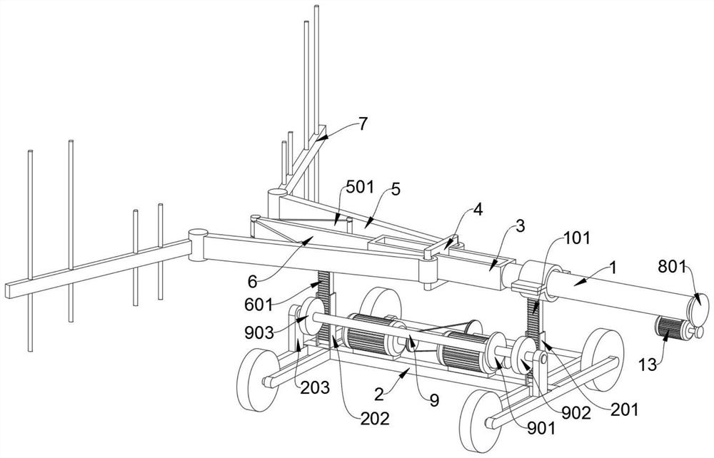
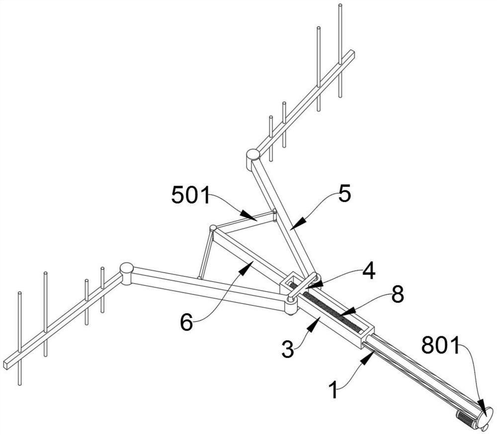
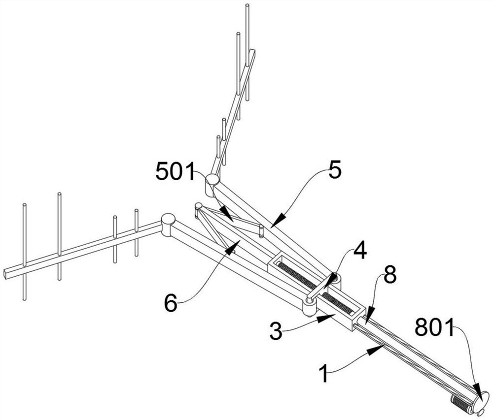
[0037]The present invention provides an electronic product detecting device antenna holder, including the rear frame body 1, the slider 4, the adjustment lever 5, the positioning plate 6, the adjustment shaft 8, the lifting device 9, the synchronization device 10, the mobile motor 11, the lifting motor 12 The angle adjustment motor 13; the front side of the rear body 1 is fixedly connected to the carriage 3; the slider 4 is slidably connected to the carriage 3; the adjustment rod 5 is two, respectively, respectively, on both sides of the slider 4, and adjust the rod 5 The other end is attached to the antenna 7; the adjustment lever 5 includes a plate 501, and the middle of the adjustment lever 5 is attached to the branch plate 501, and the adjustment lever 5 is a rectangular rod having a ring buckle of the rear end, and the plate 501 is A rectangular thin plate, the adjustment rod of this structure is likeFigure 5 As shown, due to the movem...


PUM


Abstract

The invention provides an antenna support for electronic product detection equipment. The antenna support comprises a rear support body, a sliding block, adjusting rods, a positioning plate, an adjusting shaft, a lifting device, a synchronizing device, a moving motor, a lifting motor and an angle adjusting motor, wherein the front of the rear support body is fixedly connected with a sliding frame;the sliding block is connected to the sliding frame in a sliding mode; the two adjusting rods are hinged to the two sides of the sliding block respectively, and the other end of each adjusting rod isprovided with an antenna; the adjusting rod comprises a supporting plate, and the middle of the adjusting rod is connected with the supporting plate in a hinged mode; and one end of the positioning plate is fixedly connected to the front of the sliding frame, the other end of the positioning plate is hinged to the supporting plate, two rollers rotate to drive the whole equipment support to move at a constant speed when the synchronizing device rotates, and the function of constant-speed action can be achieved. Compared with a traditional antenna support, the movement is more uniform in the position adjusting process, the shaking of the upper antenna is reduced, slow change conditions of received signals can be observed conveniently through constant-speed movement, and the position where the signals occur can be captured easily.

Description

Technical field[0001]The present invention belongs to the detecting device antenna stent technology, and more particularly to an antenna bracket for electronic product detection equipment.Background technique[0002]The antenna is a transducer that transforms the guide wave propagating on the transmission line to the electromagnetic wave propagating in the unbounded medium, or performs reverse transformation. The components used to transmit or receive electromagnetic waves in the radio apparatus. Radio communication, broadcast, television, radar, navigation, electronic confrontation, remote sensing, radio astronomical engineering system, all of which use electromagnetic waves to deliver information, relying on the antenna to work. Further, in terms of electromagnetic wave transmission energy, the non-signal energy radiation also needs an antenna. The general antenna is reversible, i.e., the same pair can be used as a transmit antenna, and can also be used as a receiving antenna, so th...

Claims


Application Information

Patent Timeline
Patent Type & Authority Patents(China)
IPC IPC(8): H01Q1/12H01Q3/08G01R1/04
CPCG01R1/0408H01Q1/12H01Q3/08
Inventor 项青松陈毓萧甦
Owner 浙江001集团有限公司
Why Eureka
Try Eureka