Board to Board Plug

A board-to-board and plug technology, applied in the direction of coupling devices, contact parts, electrical components, etc., can solve the problems of small space for welding positions, limited supporting force of covering parts, changes in relative positions, etc., and achieve the effect of preventing left and right shaking

Active Publication Date: 2021-06-15
KUNSHAN KTA COMM TECH CO LTD
View PDF6 Cites 0 Cited by
  • Summary
  • Abstract
  • Description
  • Claims
  • Application Information

AI Technical Summary

Problems solved by technology

The conductive terminal includes a welding part extending to the plug body and welded with the core wire of the cable. The conductive terminal includes a ground terminal and a signal terminal arranged at intervals. The ground terminal and the signal terminal form a row in the lateral direction Arrangement, the soldering position space is small, it is easy to produce technical problems such as solder jumping tin lead to short circuit or the pad is too small to stabilize the soldering
[0003] At the same time, the lateral sides of the shielding shell are bent downwards to cover the covering part above the cable bracket holding several cables, and the covering part is supported by the extension arm part and the cable bracket formed by the backward extension of the plug body part of the covering part, the supporting force for the covering part is limited, and it is easy to cause the covering part to collapse due to excessive bending during bending
[0004] Moreover, the positioning of the plug body and the shielding shell is through the front end of the plug body providing a limit protrusion, and a limit notch is set at the front end of the shielding shell. When assembling, the plug body is pushed forward to make the limit The protruding part snaps into the limit gap for positioning, and the precise positioning of the remaining parts needs to be positioned by covering the covering part and fixing by spot welding. During this period, the relative position of the plug body and the shielding shell is likely to change and eventually Affect product accuracy

Method used


Image

  • Board to Board Plug
  • Board to Board Plug
  • Board to Board Plug

Examples


Embodiment Construction

[0032] In order to make the purpose, technical solution and advantages of the present application clearer, the technical solution of the present application will be clearly and completely described below in conjunction with specific embodiments of the present application and corresponding drawings. Apparently, the described embodiments are only some of the embodiments of the present application, rather than all the embodiments.

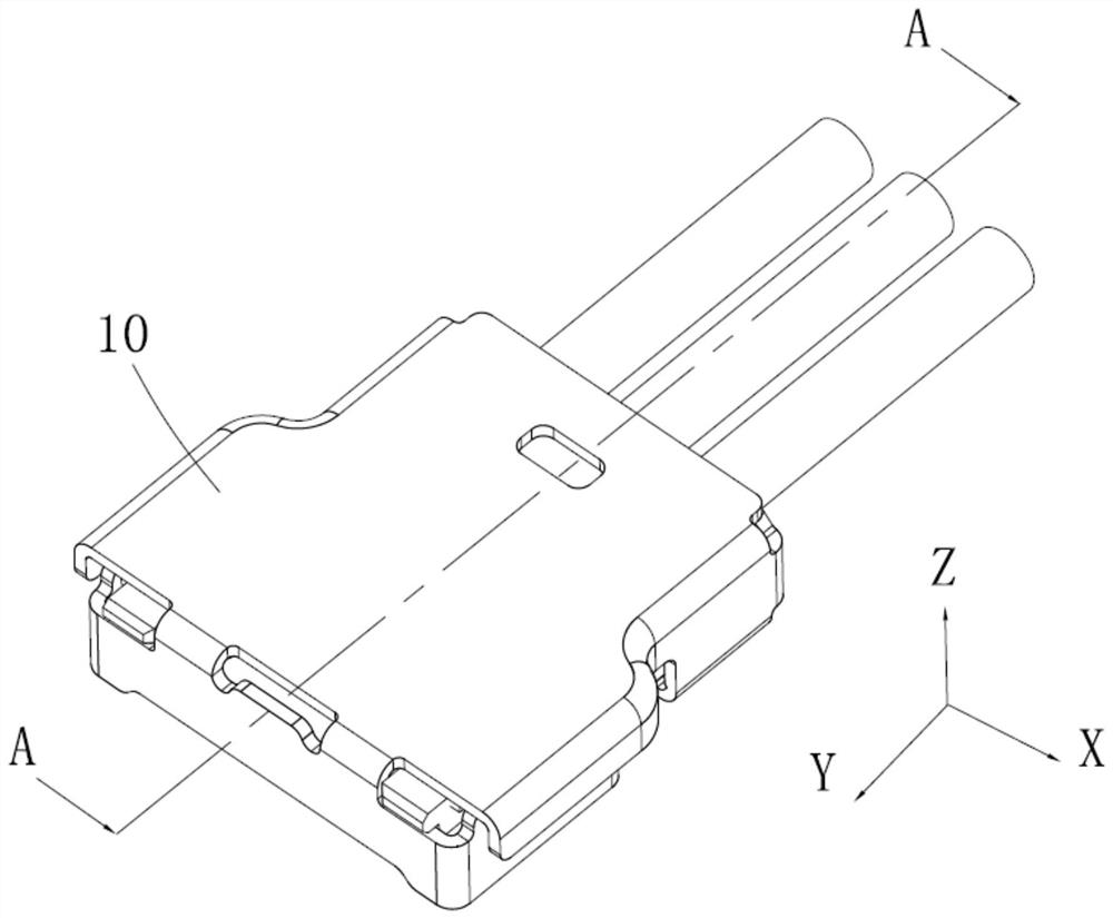
[0033] This application is based on figure 1 The indicated X direction is the front in the left-right direction (horizontal direction), the Y direction is the front in the front-rear direction (vertical direction), and the Z direction is the upper direction in the vertical direction (vertical direction).

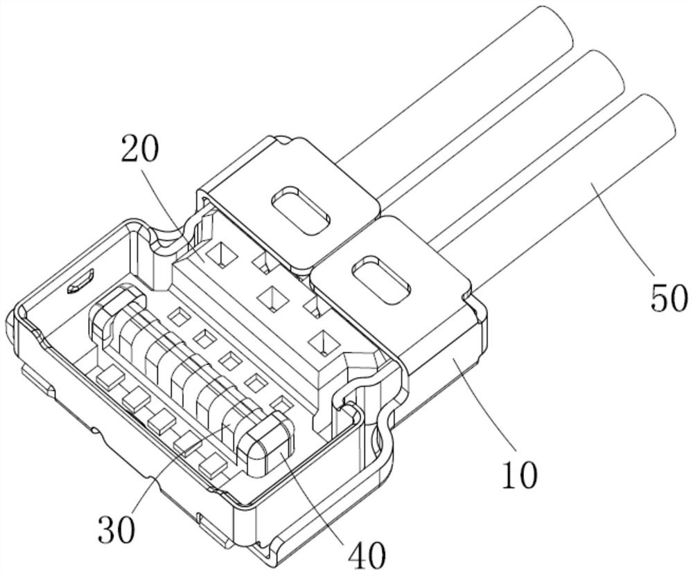
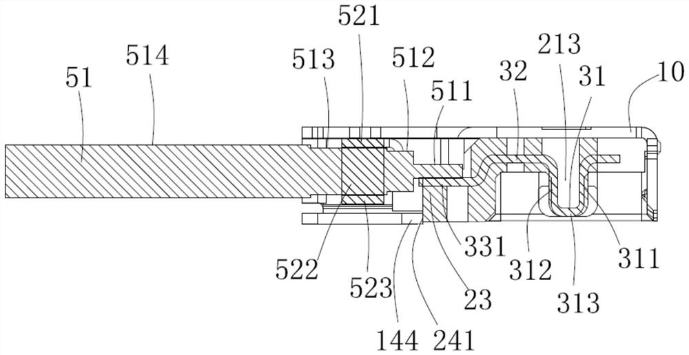
[0034] see figure 1 , figure 2As shown, the board-to-board plug of this application includes a plug body 20, a plurality of plug terminals 30 and metal reinforcements 40 integrally formed in the plug body 20, a cable assembly 50 connected to the ...


PUM


Abstract

A board-to-board plug, comprising several plug terminals, a plug body holding the several plug terminals as a whole, a cable assembly located behind the plug body and connected to the plug terminals, and a A shielding shell, the plug body includes a base and an extension formed from the base, the extension includes a protruding portion protruding downwards and a soldering station at the top, the shielding shell includes a base that covers the plug The covering top plate on the top surface of the body, the covering front wall formed by bending downwards from the front end of the covering top plate, the covering side walls formed by bending backwards from both lateral ends of the covering front wall, and Bending down the protective part located outside the covering side wall, the protective part includes a clamping part that is relatively bent and covers the soldering platform, and the lower surface of the protruding part is formed to be supported by the clamping part limit steps. The application can effectively limit the plug body.

Description

technical field [0001] The present application relates to the field of electrical connectors, in particular to a board-to-board plug. Background technique [0002] Since traditional single-channel coaxial connectors can no longer meet the communication needs of consumer electronics devices such as smartphones, multi-channel high-frequency transmission connectors in the form of board-to-board have emerged. CN110474201A discloses a board-to-board plug, including a plug body formed with several conductive terminals, a cable assembled at the tail of the plug body and welded to the conductive terminals, and a shielding shell covering the plug body. The conductive terminal includes a welding part extending to the plug body and welded with the core wire of the cable. The conductive terminal includes a ground terminal and a signal terminal arranged at intervals. The ground terminal and the signal terminal form a row in the lateral direction Arrangement, the welding position space i...

Claims


Application Information

Patent Timeline
Patent Type & Authority Patents(China)
IPC IPC(8): H01R13/502H01R13/648H01R13/04
CPCH01R13/04H01R13/502H01R13/648
Inventor 张自财白攀
Owner KUNSHAN KTA COMM TECH CO LTD
Why Eureka
Try Eureka