Method and device for joining hot slabs by means of friction welding

A slab and equipment technology, applied in welding equipment, non-electric welding equipment, welding/welding/cutting items, etc., can solve the problem that the welding result cannot be regarded as ideal, achieve uniform welding results or connection results, and small design Cost, cost-effective effect

Inactive Publication Date: 2020-06-16
SMS GRP GMBH
View PDF15 Cites 0 Cited by
  • Summary
  • Abstract
  • Description
  • Claims
  • Application Information

AI Technical Summary

Problems solved by technology

For these reasons, the welding results of the direct friction welding joining method cannot be regarded as ideal

Method used


Image

  • Method and device for joining hot slabs by means of friction welding
  • Method and device for joining hot slabs by means of friction welding

Examples


Embodiment Construction

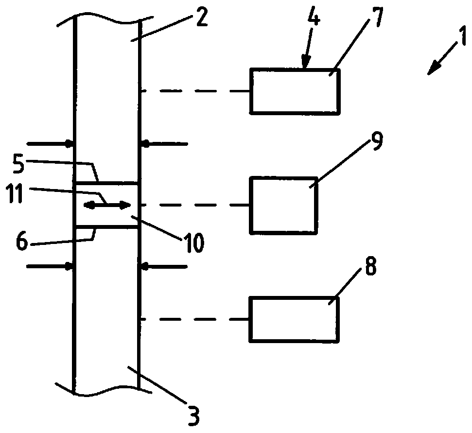
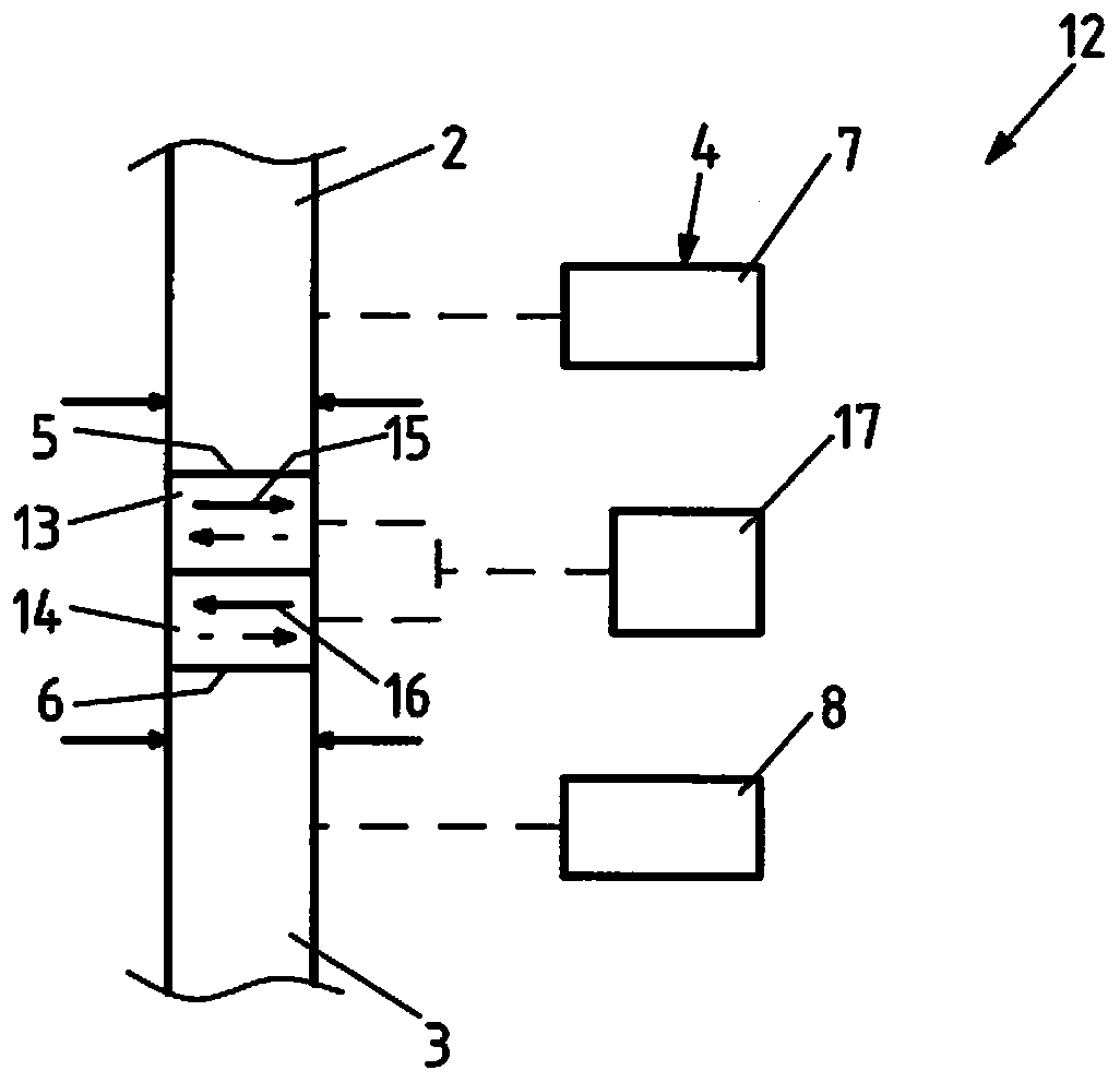
[0031] figure 1 A schematic illustration of an exemplary embodiment of a device 1 according to the invention is shown for connecting hot slabs 2 and 3 which can be fed successively to at least one rolling stand (not shown).

[0032] The plant 1 comprises a clamping device 4 for clamping a first hot slab 2 and a second hot slab 3 such that the connecting sides 5 and 6 of the hot slabs 2 and 3 face each other ground and spaced apart from each other. For this purpose, the clamping device 4 includes a separate clamping unit 7 or 8 for each hot slab 2 or 3 .

[0033] Furthermore, the device 1 comprises a vibrating device 9 for holding a single metallic intermediate part 10 between the connecting sides 5 and 6 and for generating the , as far as possible or exactly parallel to the oscillating movement of the connection sides 5 and 6 . In this case, the clamping device 4 presses the connecting sides 5 and 6 against the intermediate part 10 at least during the oscillating movement o...


PUM


Abstract

The invention relates to a method for joining hot slabs (2, 3), which can be fed in succession to at least one roll stand. In order to enable the joining of the hot slabs (2, 3) with lower energy demand and less design complexity and better joining results, joining sides (5, 6) of the hot slabs (2, 3) facing each other are, by pendular friction welding and / or vibration friction welding: simultaneously integrally bonded to a single metal intermediate piece (10) arranged between the joining sides (5, 6) , by oscillatingly moving the intermediate piece (10) at least largely parallel to the joining sides (5, 6), while the joining sides (5, 6) are pressed against the intermediate piece (10) and are held stationary; or simultaneously integrally bonded to at least one separate metal intermediatepiece (13, 14) each, said intermediate pieces being arranged between the joining sides (5, 6), by pressing the intermediate pieces (13, 14) arranged in series between the joining sides (5, 6) and oscillatingly moving said intermediate pieces at least largely parallel to the joining sides (5, 6) and oppositely to each other, while the joining sides (5, 6) are pressed against the intermediate pieces(13, 14) and held stationary.

Description

technical field [0001] The invention relates to a method and a device for joining hot slabs which can be fed successively to a rolling stand. Background technique [0002] It is known to connect hot slabs to one another in order, for example, to be able to carry out continuous hot rolling of successive hot slabs without interruptions for threading or tailing the corresponding hot slabs in the rolling stand or rolling train rolling process. Thinner final thicknesses can be achieved due to the elimination of the piercing process. Furthermore, the risk of so-called rolling instabilities and the risk of shifting of the rolling stock is reduced. That is, because no hot slab penetration is required or flick This also reduces the number of rejects that are usually associated with piercing or tailing, due to the separation of the end sections of the hot slab, which are not yet available at the beginning of rolling or at the end of rolling. is no longer reduced to the desired ...

Claims


Application Information

Patent Timeline
IPC IPC(8): B23K20/12B23K20/16B21B15/00
CPCB21B15/0085B23K20/1205B23K20/129B23K20/16B23K2103/18
Inventor M·舍尔曼
Owner SMS GRP GMBH
Why Eureka
Try Eureka