Self walking soil processing machine

A soil treatment, self-propelled technology, applied in soil protection, earth mover/excavator, mixer, etc., can solve the problem of low mechanical efficiency

Inactive Publication Date: 2003-07-02
NIHON KENKI CO LTD
View PDF0 Cites 3 Cited by
  • Summary
  • Abstract
  • Description
  • Claims
  • Application Information

AI Technical Summary

Problems solved by technology

[0017] However, such small plants operate with mechanical inefficiencies if they are equipped with fixed soil treatment machines in each plant

Method used


Image

  • Self walking soil processing machine
  • Self walking soil processing machine
  • Self walking soil processing machine

Examples


Embodiment Construction

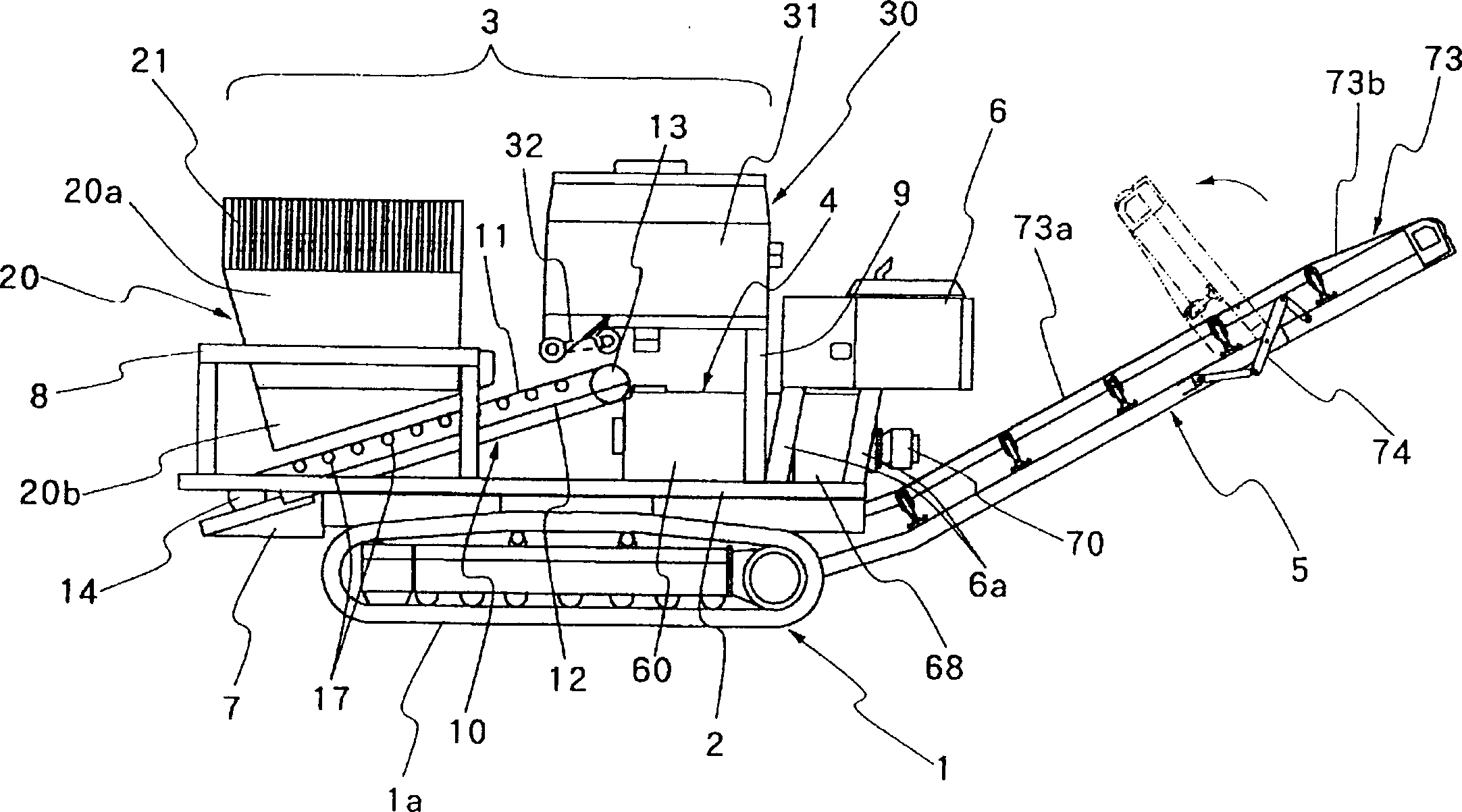
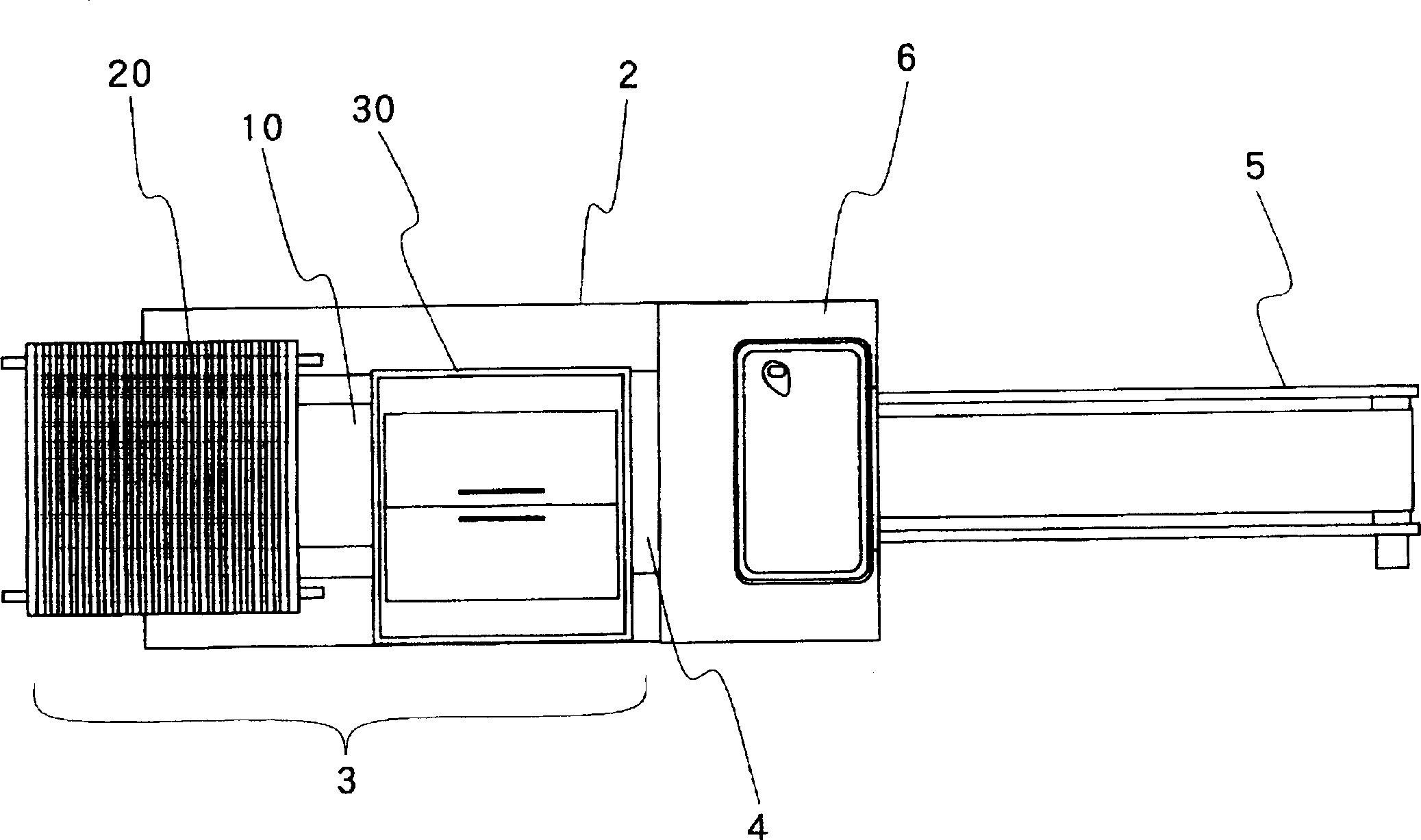
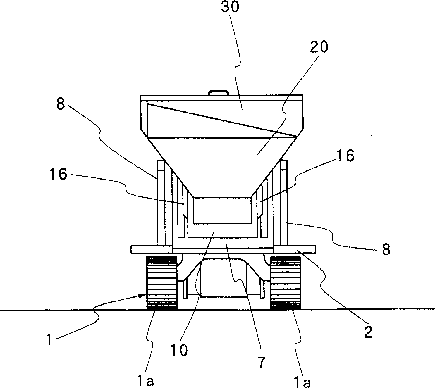
[0054] The present invention will be described in detail below based on preferred embodiments shown in the drawings. Figure 1 to Figure 3 Shown is the vehicle-mounted or self-propelled soil treatment machine of the present invention. figure 1 Here, 1 denotes the basic carrier of the machine, which is a crawler-type vehicle with a crawler 1a, which is well known in the prior art. Since the foundation carrier 1 is a crawler type, when the excavated soil is thrown into the machine, it is possible to prevent the overall machine from becoming unstable due to, for example, loading shock. However, in the case where it is arranged to continuously load the excavated soil with a conveyor or the like, the base carrier may also be a wheeled vehicle.

[0055]A soil feed section 3 and a soil treatment section 4 are installed on the main frame 2 of the foundation carrier 1, and the soil feed section 3 is located at the front of it. figure 1 The soil treatment section 4 is located after the fe...


PUM


Abstract

A vehicular automotive soil treating machine having a main frame structure provided on an automotive drive means to support thereon a soil feeding stage including at least a soil hopper and an additive hopper, a soil processing stage including a soil processing trough which is internally provided with a mixing means for mixing soil and additive material while being transferred from one to the other end of the soil processing trough, and a processed soil discharging stage including a soil discharging conveyer. The soil processing trough is provided with an inlet opening on the upper side of its fore end portion and an outlet opening on the bottom side of its rear end portion.

Description

Technical field [0001] The present invention generally relates to a soil treatment machine, which is used to treat the soil and strengthen the loose soil foundation by improving the soil structure and quality to meet the needs of special use purposes, in particular to a self-propelled or vehicle-mounted A soil treatment machine, which can walk along the surface of the land or area during the soil treatment process. Background technique [0002] When excavating land, for example, to lay gas pipes, water pipes or sewer pipes, or for road construction work or other foundation construction, it is very desirable to use cleared soil that has not been treated in any way to backfill the excavated ground . However, in some cases, it was found that the excavated soil was not suitable for backfilling. In this case, it is necessary to discard the excavated soil and backfill the excavated ground with soil of better quality or characteristics. For example, in some cases, the excavated soil con...

Claims


Application Information

Patent Timeline
Patent Type & Authority Patents(China)
IPC IPC(8): E02F7/00B01F13/00E02D3/00E02D3/12E02F5/22E02F7/02E02F7/06
CPCE02F5/226E02F7/06E02F7/02E02D3/00E02F7/00B01F33/00
Inventor 桥本久仪佐藤藤男山本康晴村井俊和三浦哲志郎中桐史树草木贵巳关野聪广濑清信水野良夫伊藤伸男福泽秀喜
Owner NIHON KENKI CO LTD
Why Eureka
Try Eureka