Tumor radiotherapy machine

A tumor radiation and treatment machine technology, applied in radiation therapy, treatment, X-ray/γ-ray/particle irradiation therapy, etc., can solve the problems of different simulated positioning areas and radiation damage to the body, so as to prevent damage and achieve optimal tumor treatment. effect of effect

Inactive Publication Date: 2020-06-19
谷昌德
View PDF1 Cites 1 Cited by
  • Summary
  • Abstract
  • Description
  • Claims
  • Application Information

AI Technical Summary

Problems solved by technology

[0004] The above-mentioned technical solution has at least the following defects: since the positioning light source 4 is located below the radiation light source 2 when simulating the positioning of the lesion area of ​​the patient, the actual radiation area of ​​the radiation light source 2 is different from the simulated positioning area of ​​the positioning light source 4, Specifically, the actual radiation area of ​​the radiation source 2 is larger than the simulated positioning area of ​​the positioning light source 4, so that the radiation source 2 will irradiate more normal tissue cells, which will cause unnecessary radiation damage to the patient's body. Therefore, it is urgent to improve the

Method used


Image

  • Tumor radiotherapy machine
  • Tumor radiotherapy machine
  • Tumor radiotherapy machine

Examples


Embodiment Construction

[0022] The following will clearly and completely describe the technical solutions in the embodiments of the present invention with reference to the drawings in the embodiments of the present invention. It should be noted that if there is a directional indication (such as up, down, left, right, front, back...) in the embodiment of the present invention, the directional indication is only used to explain the position in a certain posture (as shown in the accompanying drawing). If the specific posture changes, the directional indication will also change accordingly. In addition, if there are descriptions involving "first", "second" and so on in the embodiments of the present invention, the descriptions of "first", "second" and so on are only for descriptive purposes, and should not be interpreted as indicating or implying Its relative importance or implicitly indicates the number of technical features indicated. Thus, the features defined as "first" and "second" may explicitly o...


PUM


Abstract

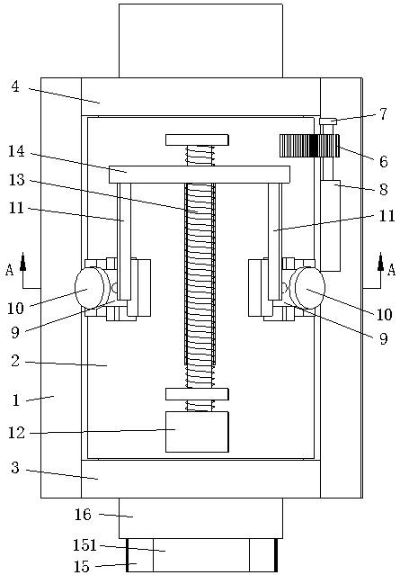
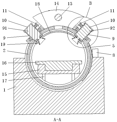
The invention relates to the technical field of medical equipment and in particular relates to a tumor radiotherapy machine which comprises a base, a rotating cylinder, a second driving mechanism anda return mechanism, wherein connecting parts are hinged with the side wall of the rotating cylinder; the number of the connecting parts is two; the two connecting parts are respectively provided witha radiation light source and a positioning light source and are distributed at an interval on a circle along the axis of the rotating cylinder; the minimum central angle of centers of the positioninglight source and the radiation light source on the circle is a; the second driving mechanism is used for driving the two connecting parts to move and used for enabling the radiation light source and the positioning light source to swing synchronously with an equal amplitude; and the return mechanism is used for controlling the first driving mechanism and used for enabling the rotating cylinder torotate for a set angle a along a first direction so as to move the radiation light source to a position of the positioning light source before return. By adopting the tumor radiotherapy machine provided by the invention, the deviation of an actual radiation area of the radiation light source and a simulated positioning area of the positioning light source can be reduced.

Description

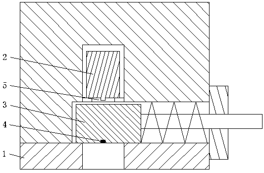
technical field [0001] The invention relates to the technical field of medical equipment, in particular to a tumor radiotherapy machine. Background technique [0002] Malignant tumors are one of the main causes of death in our country. At present, there is no specific treatment for malignant tumors. Radiation is generally used for treatment, that is, high-energy radiation is used to irradiate the tumor lesion area to achieve the purpose of treatment. In radiotherapy A tumor radiation therapy machine is generally used during the procedure. [0003] In the patent No. CN104548370B, a tumor radiotherapy machine is disclosed, such as figure 1 As shown, the tumor radiotherapy machine includes a base 1, a radiation source 2 and a positioning light source 4. The base 1 is provided with a radiation hole 5 and a radiation hole switch door 3 that can be opened and closed relative to the radiation hole 5. The positioning light source 4 is arranged on the radiation hole 5. On the hole ...

Claims


Application Information

Patent Timeline
Patent Type & Authority Applications(China)
IPC IPC(8): A61N5/10
CPCA61N5/1049A61N2005/1092
Inventor 谷昌德
Owner 谷昌德
Why Eureka
Try Eureka