
Synchronous manufacturing method for main and auxiliary hinge pieces

A manufacturing method and synchronous technology, applied in the direction of folding boards, hinges with pins, building structures, etc., can solve the problems of poor horizontal linearity of reels, low production efficiency, poor flatness, etc., to increase the contact area and strengthen Structural strength and the effect of improving the service life

Active Publication Date: 2020-06-19
广东钢绅士金属制品有限公司
View PDF5 Cites 0 Cited by
  • Summary
  • Abstract
  • Description
  • Claims
  • Application Information

AI Technical Summary

Problems solved by technology

Not only the manufacturing process is cumbersome and the production efficiency is low, but also the problem of large color difference in the surface treatment of the sub-page and the main page due to different batches, such as electroplating, spraying, etc., is very easy to occur, especially the method of separate production is easy to make the horizontal linearity of the reel poor. , the rotation is not flexible, and the flatness is poor;
[0004] In addition, the mother and child hinges are easy to use and install, and the noise is low. Because the sudden force of opening and closing the door will greatly affect the service life of the mother and child hinges, accordingly, the present invention provides a synchronous manufacturing method of the mother and child hinges

Method used


Image

  • Synchronous manufacturing method for main and auxiliary hinge pieces
  • Synchronous manufacturing method for main and auxiliary hinge pieces
  • Synchronous manufacturing method for main and auxiliary hinge pieces

Examples


Embodiment Construction

[0027] In order to make the technical means, creative features, goals and effects achieved by the present invention easy to understand, the present invention will be further described below in conjunction with specific embodiments.

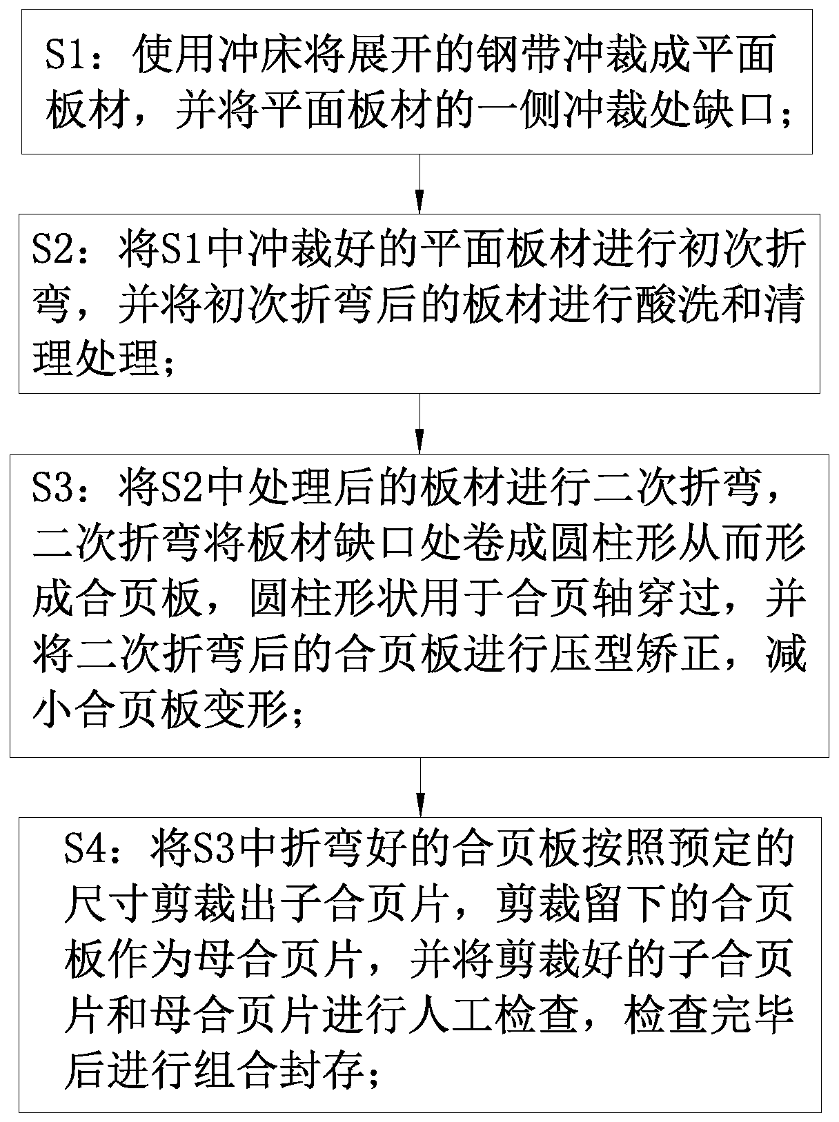
[0028] Such as Figure 1-5 As shown, a synchronous manufacturing method of a mother-child hinge according to the present invention, the method steps are as follows:

[0029] S1: Use a punching machine to punch the unfolded steel strip into a flat plate, and punch a notch on one side of the flat plate; punch the plate in advance, so as to facilitate the rapid development of the next process;

[0030]S2: Bending the flat sheet blanked in S1 for the first time, and pickling and cleaning the sheet after the initial bending; pickling and cleaning the sheet after the initial bending to improve the cleanliness of the sheet and prevent oxidation;

[0031] S3: Perform secondary bending on the plate processed in S2. The secondary bending rolls the notch o...


PUM


Abstract

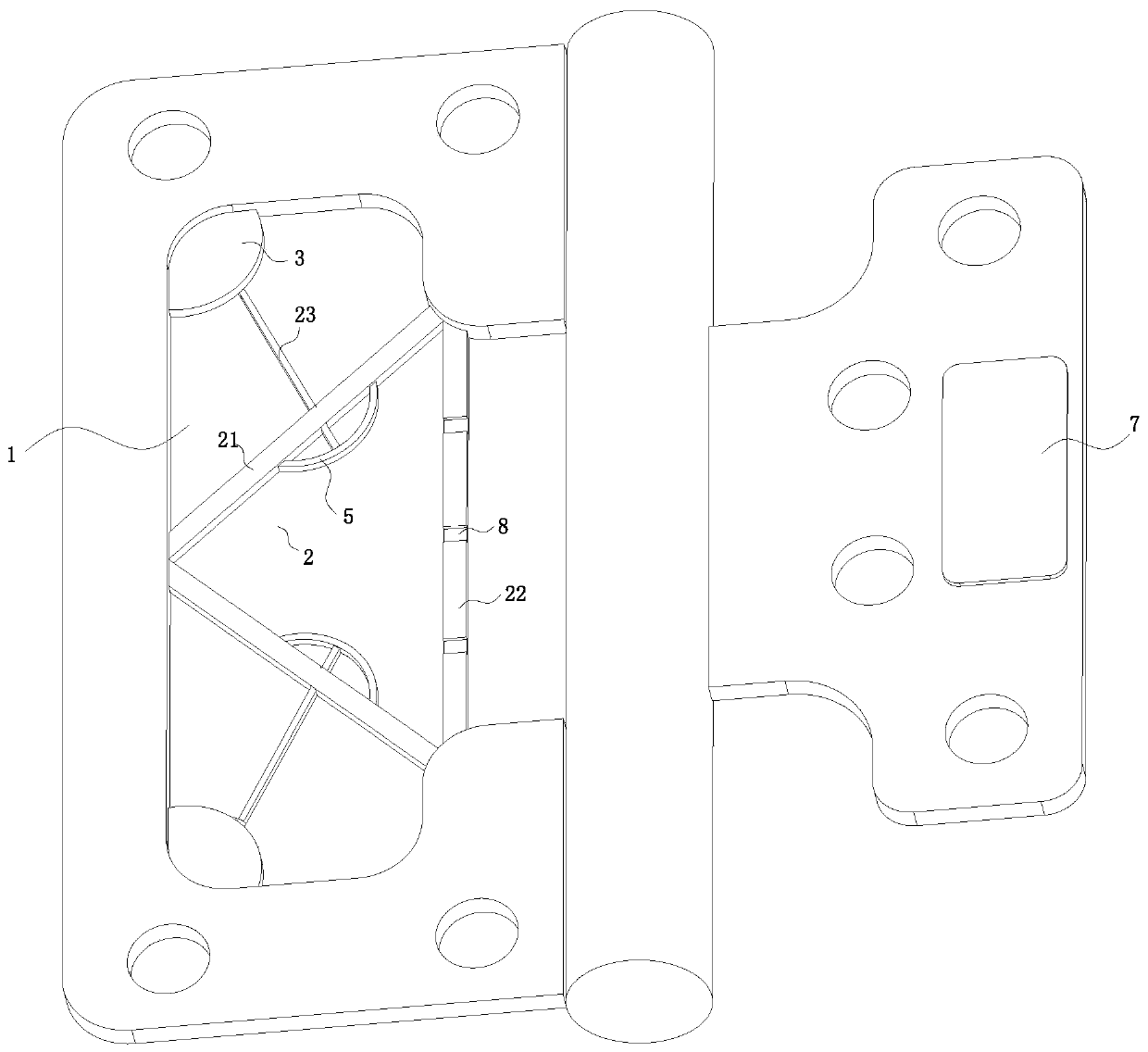
The invention belongs to the technical field of hinge manufacture, and particularly provides a synchronous manufacturing method for main and auxiliary hinge pieces. According to the method, a clamp groove corresponding to the auxiliary hinge piece is formed in the main hinge piece; a gap is formed between the clamp groove and the auxiliary hinge piece, and a supporting unit is fixedly mounted in the clamp groove; the supporting unit is used for supporting the main auxiliary piece and comprises two supporting plates, a reinforcing rod and a reinforcing rope; the two supporting plates are symmetrically distributed on two sides of the clamp groove, and the other ends of the two supporting plates are fixedly connected through the reinforcing rod; and the two supporting plates and the reinforcing rod constitute a triangular shape. The supporting unit is fixedly mounted in the clamp groove of the main hinge piece, the supporting unit can support the main hinge piece when the auxiliary hingepiece coincides with the main hinge piece by means of supporting force of the supporting unit, so that two-way force of the main hinge piece is reduced, structural strength of the main hinge piece isenhanced, and the service life of the main and auxiliary hinge pieces is prolonged.

Description

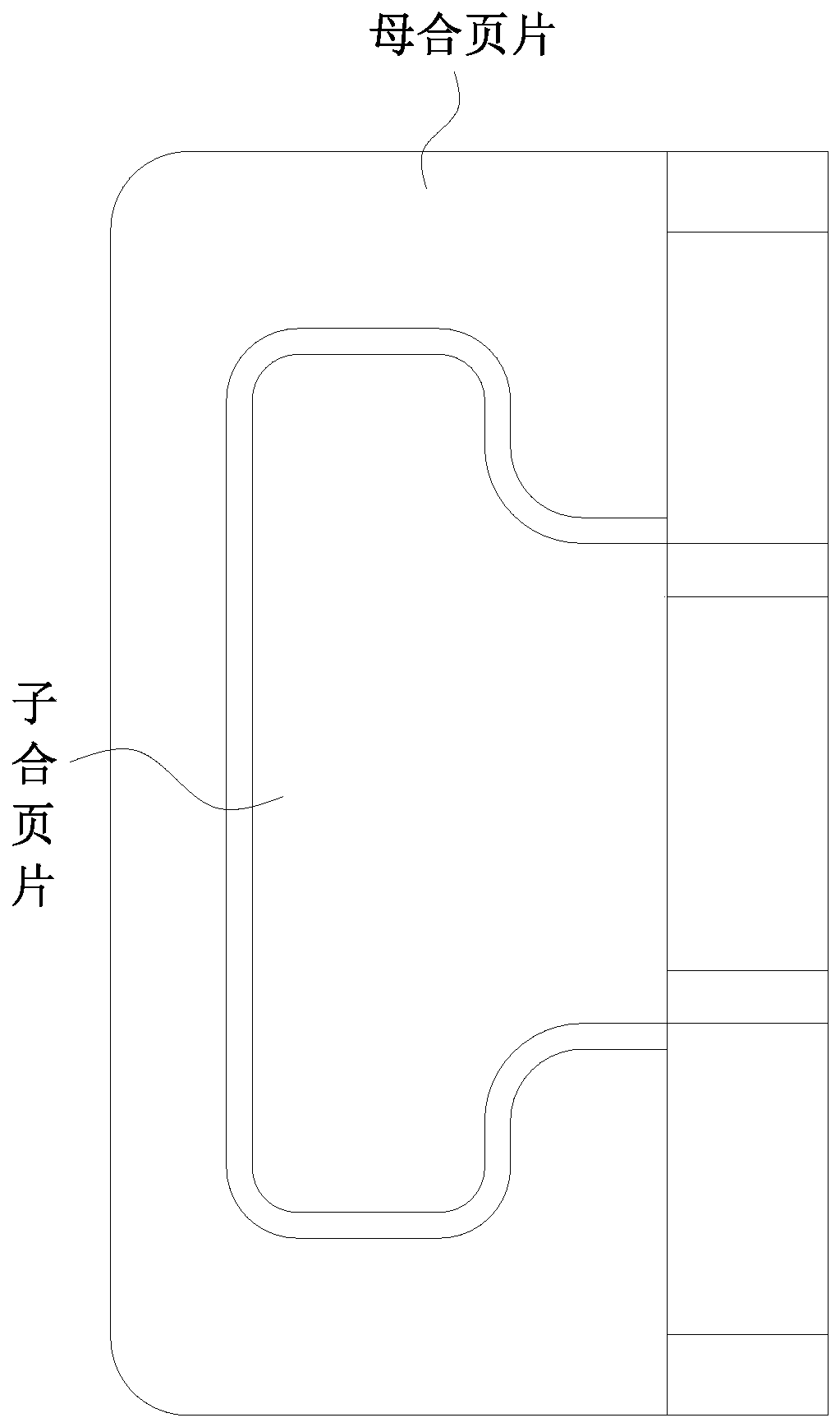
technical field [0001] The invention belongs to the technical field of hinge manufacturing, in particular to a synchronous manufacturing method of mother-child hinge pieces. Background technique [0002] The mother-child hinge cylinder includes a hinge piece and a hinge shaft. Its main feature is that the hinge piece is divided into a child leaf piece and a mother leaf piece. Both the child leaf piece and the mother leaf piece are installed on the hinge shaft and form a hinge connection. , and are all in the same tangential direction of the hinge axis, the sub-leaf is shaped like a part of the mother leaf "hollowed out", the sub-leaf can rotate 360° around the central axis, and can be fitted into the mother leaf, Form a complete sheet. Compared with the casement hinge, the mother-child hinge is suitable for installation in the center, depth, and edge of the door frame. It does not need to dig out the fixed hinge part (slot) of the door leaf like the casement hinge, and the ...

Claims


Application Information

Patent Timeline
IPC IPC(8): B21D35/00B21D53/40E05D3/02E05D5/02E05F5/02E05F5/06
CPCB21D35/002B21D53/40E05D3/02E05D5/02E05F5/02E05F5/06E05Y2900/132
Inventor 刘根王文昭张新
Owner 广东钢绅士金属制品有限公司
Learn More