AI technical title is built by Patsnap AI team. It summarizes the technical point description of the patent document.
A technology of CNC lathes and lathes, applied in the field of CNC lathes, can solve problems such as bolt loosening, nut pair translation obstruction, dirt, etc., and achieve the effects of avoiding blockage, smooth translation, and preventing scaling
Active Publication Date: 2021-05-18
邵阳永腾金属制品有限公司
View PDF8 Cites 1 Cited by
Summary
Abstract
Description
Claims
Application Information
AI Technical Summary
This helps you quickly interpret patents by identifying the three key elements:
Problems solved by technology
Method used
Benefits of technology
Problems solved by technology
[0003] The screw is an important component of the CNC lathe. The movement of the tool holder is realized by the cooperation of the screw and the nut pair. However, the existing screw is exposed, and the screw has a thread groove. When the workpiece is processed, cutting chips will be generated, and the cutting chips will also fall into the thread groove, which will hinder the translation of the nut pair. When idle, the dust and impurities in the air will also fall into the thread groove. , will make dust and impurities adhere to the thread groove, forming dirt, which is not conducive to the translation of the nut pair, and it is inconvenient to clean and descale the screw rod;
[0004] In addition, the blades are simply fixed by bolts. Since the blades are subjected to external processing forces and resonance forces during processing, the bolts will loosen, which in turn will cause the blades to loosen, which is not conducive to the processing of the workpiece.
Method used
Image
Click on the blue label to locate the original text in one second.
Reading with bidirectional positioning of images and text.
Examples
Embodiment 1
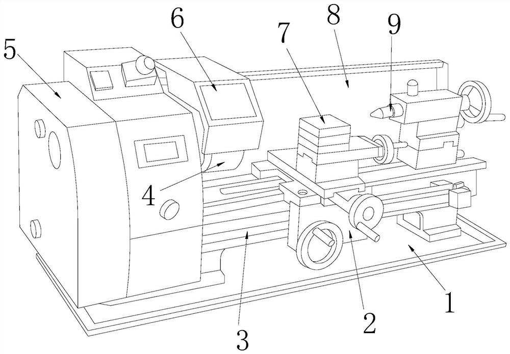
[0043] see figure 1 , the present invention provides a technical solution for a numerically controlled lathe: please refer to Figure 1-3 , the present invention provides a technical solution for a CNC lathe: its structure includes a base 1, a moving assembly 2, a screw assembly 3, a chuck 4, a lathe body 5, a dust cover 6, a lathe tool rest 7, a guard plate 8, Tailstock jacking mechanism 9, described base 1 is provided with lathe body 5, and described lathe body 5 is fixed with guard plate 8, and described lathe body 5 is equipped with chuck 4, and above described chuck 4 is provided with dust-proof Cover 6, one side of the chuck 4 is provided with a tailstock jacking mechanism 9, and the tailstock jacking mechanism 9 is movably connected with the lathe body 5, and the lathe body 5 is provided with a screw assembly 3, and the wire The rod assembly 3 is connected with a mobile assembly 2, and the movable assembly 2 is fixed with a liftable lathe tool rest 7;
[0044] see ...
Embodiment 2
[0052] see figure 1 , the present invention provides a technical solution for a CNC lathe: its structure includes a base 1, a moving assembly 2, a screw assembly 3, a chuck 4, a lathe body 5, a dust cover 6, a lathe tool rest 7, a guard plate 8, Tailstock jacking mechanism 9, described base 1 is provided with lathe body 5, and described lathe body 5 is fixed with guard plate 8, and described lathe body 5 is equipped with chuck 4, and above described chuck 4 is provided with dust-proof Cover 6, one side of the chuck 4 is provided with a tailstock jacking mechanism 9, and the tailstock jacking mechanism 9 is movably connected with the lathe body 5, and the lathe body 5 is provided with a screw assembly 3, and the wire The rod assembly 3 is connected with a mobile assembly 2, and the movable assembly 2 is fixed with a liftable lathe tool rest 7;
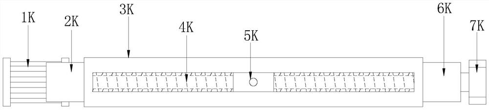
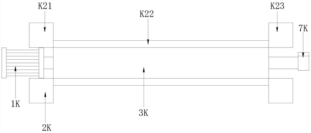
[0053] see figure 2 , Figure 4 , the screw assembly 3 includes a micro motor 1K, No. 1 dust-proof device 2K, dust-proof box 3K, ...
PUM
Abstract
The invention discloses a numerically controlled lathe, the structure of which comprises a base, a moving assembly, a screw assembly, a chuck, a lathe body, a dust cover, a lathe tool holder, a guard plate, and a tailstock jacking mechanism, and a lathe is arranged on the base The main body, the lathe body is fixed with a guard plate. Compared with the prior art, the beneficial effect of the present invention is that the screw assembly of the present invention adopts a new structure setting, which is enough to hide the screw, avoid the exposure of the screw, and effectively prevent lathe processing. The generated debris and external dust fall into the thread groove of the screw rod, avoiding the blockage of the thread groove of the screw rod, preventing the scaling of the screw groove, and making the translation of the moving component smooth and unimpeded, so that there is no need to clean and descale the screw rod. The blade mounting seat adopts a new structure setting to achieve multiple fixes, effectively prevent the bolts and blades from loosening, and facilitate the processing of the workpiece by the blade.
Description
technical field [0001] The invention relates to the technical field of numerically controlled lathes, in particular to a numerically controlled lathe. Background technique [0002] CNC lathe is one of the most widely used CNC machine tools at present. It is mainly used for cutting the inner and outer cylindrical surfaces of shaft parts or disk parts, the inner and outer conical surfaces of arbitrary cone angles, the complex rotary inner and outer curved surfaces, cylinders, and conical threads, etc., and can perform grooving, drilling, reaming, and reaming. Holes and borings etc. [0003] The screw is an important component of the CNC lathe. The movement of the tool holder is realized by the cooperation of the screw and the nut pair. However, the existing screw is exposed, and the screw has a thread groove. When the workpiece is processed, cutting chips will be generated, and the cutting chips will also fall into the thread groove, which will hinder the translation of the ...
Claims
Application Information
Patent Timeline
Application Date:The date an application was filed.
Publication Date:The date a patent or application was officially published.
First Publication Date:The earliest publication date of a patent with the same application number.
Issue Date:Publication date of the patent grant document.
PCT Entry Date:The Entry date of PCT National Phase.
Estimated Expiry Date:The statutory expiry date of a patent right according to the Patent Law, and it is the longest term of protection that the patent right can achieve without the termination of the patent right due to other reasons(Term extension factor has been taken into account ).
Invalid Date:Actual expiry date is based on effective date or publication date of legal transaction data of invalid patent.

