Walking machine, and driving braking system and traveling braking method thereof

A braking system and mechanical technology, applied in the directions of roads, road repair, roads, etc., can solve the problems of brake pad breakage, high cost, and reduced displacement, and achieve the effect of avoiding brake pad breakage, simple structure and low cost.

Inactive Publication Date: 2020-06-19
SANY AUTOMOBILE MFG CO LTD
View PDF8 Cites 2 Cited by
  • Summary
  • Abstract
  • Description
  • Claims
  • Application Information

AI Technical Summary

Problems solved by technology

[0005] However, the first type relies on the reduction of the pump displacement to achieve service braking, which cannot meet the requirements for parking on slopes. When the parking brake is locked, the whole machine does not stop completely, and it is easy to cause failures such as breakage of the brake pads.
[0006] The second braking scheme has complex system composition and high cost

Method used


Image

  • Walking machine, and driving braking system and traveling braking method thereof
  • Walking machine, and driving braking system and traveling braking method thereof
  • Walking machine, and driving braking system and traveling braking method thereof

Examples


Embodiment 1

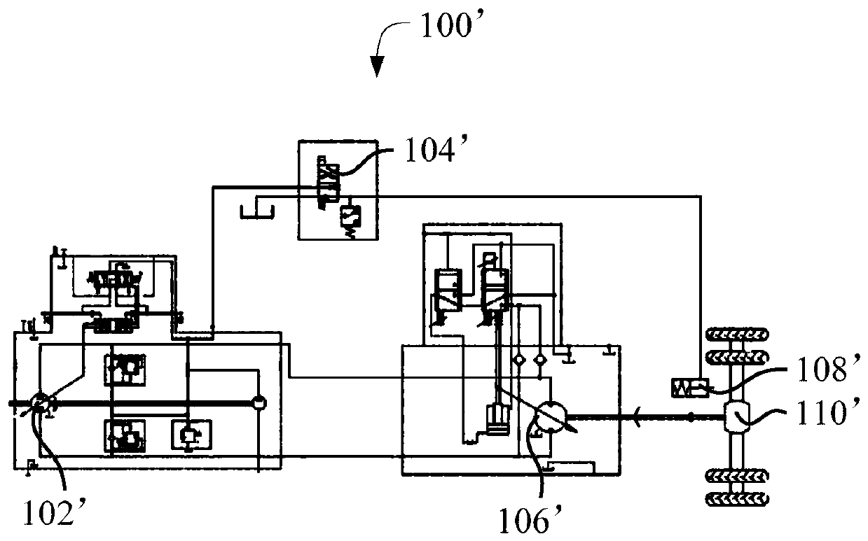
[0049] like Figure 4 As shown, according to the embodiment of the first aspect of the present invention, the present invention provides a travel braking system 100 of a mobile machine, comprising: a drive pump set 110, the drive pump set 110 includes a connected travel variable pump 112 and a charge pump 114; travel motor 130 forms a closed hydraulic circuit with the travel variable pump 112 of the drive pump group 110; the drive axle 150 is connected with the travel motor 130; the brake valve 120 is connected with the charge pump 114 of the drive pump group 110; The brake device 140 is connected with the brake valve 120, the brake device 140 is used to brake the drive axle 150, and the brake valve 120 is used to control the communication and Disconnect; the speed detection device 160 is used to detect the travel speed of the walking machine; the controller is electrically connected with the driving pump group 110, the brake valve 120 and the speed detection device 160, and w...

Embodiment 2

[0053] On the basis of Embodiment 1, further, the speed detection device 160 is a speed sensor, which is provided on the travel motor 130 or the driving axle 150 .

[0054] In this embodiment, the rotation of the rotating shaft of the traveling motor 130 drives the rotation of the rear axle in the drive axle 150, thereby realizing the traveling of the traveling machine. Therefore, the rotating speed of the traveling motor 130 or the rotating speed of the driving axle 150 can reflect the speed of the traveling machine. The travel speed, and further, the speed sensor is provided on the travel motor 130 or the transaxle 150 to accurately detect the travel speed of the travel machine.

Embodiment 3

[0056] On the basis of Embodiment 1, further, the speed detection device 160 is a strategy controller, which determines the traveling speed of the traveling machine according to the operating parameters of the traveling machine.

[0057] In this embodiment, various operating parameters of the walking machine can also reflect the running speed of the walking machine. Therefore, the strategy controller can be used to obtain the running parameters of the walking machine, and the running speed of the walking machine can be obtained through calculation.

[0058] Specifically, for example, the traveling speed of the traveling machine is calculated based on the torque on the rear axle in the transaxle 150 , the torque on the traveling motor 130 , and the like.


PUM


Abstract

The invention provides a traveling machine, and a traveling braking system and a traveling braking method thereof. The traveling braking system of the walking machine comprises: a driving pump set, wherein the driving pump set comprises a traveling variable pump and an oil supplementing pump; a travel motor forming a closed hydraulic circuit together with the traveling variable pump; a drive axleconnected with the driving motor; a brake valve connected with the oil supplementing pump; a brake device connected with the brake valve and used for braking the drive axle; a speed detection device used for detecting the running speed of the walking machine and a controller, wherein the controller reduces the displacement of the traveling variable pump to a zero value when receiving a parking instruction in the traveling process of the walking machine, after the displacement of the traveling variable pump is reduced to the zero value, the controller adjusts the displacement of the traveling variable pump according to a detection result of the speed detection device, and after the speed of the walking machine is within a preset range, the controller controls the brake valve to be started to brake the drive axle, so that the requirement of ramp parking is met.

Description

technical field [0001] The invention relates to the technical field of engineering machinery, in particular to a traveling braking system of a traveling machinery, a traveling machinery and a traveling braking method of a traveling machinery. Background technique [0002] The road roller is a kind of road construction machinery, which is mainly used for the compaction operation of the road base or surface course. At present, the road roller is usually driven by hydraulic pressure, and there are usually two braking methods. [0003] one, such as figure 1 As shown, the hydraulic system 100' consists of: hydraulic drive pump 102', parking brake control valve 104', travel motor 106', parking brake device 108', drive rear axle 110', hydraulic drive pump 102' and travel The motor 106' forms a closed system to realize the forward and backward functions of the whole machine. When accelerating, the displacement of the hydraulic drive pump 102' is gradually increased, and when brakin...

Claims


Application Information

Patent Timeline
Patent Type & Authority Applications(China)
IPC IPC(8): E01C19/23E01C19/26
CPCE01C19/23E01C19/26
Inventor 汪建利李国林朱兴
Owner SANY AUTOMOBILE MFG CO LTD
Why Eureka
Try Eureka