
Defrosting method of dehumidifier

A dehumidifier, the first technology, applied in refrigerators, heating methods, mechanical equipment, etc., can solve the problems of reduced dehumidification efficiency, easy frost formation, poor dehumidification effect, etc.

Inactive Publication Date: 2020-06-19
宁波德业日用电器科技有限公司
View PDF13 Cites 1 Cited by
  • Summary
  • Abstract
  • Description
  • Claims
  • Application Information

AI Technical Summary

Problems solved by technology

[0004] Therefore, with the expansion of the scope of use of dehumidifier products, dehumidifiers have also been used in some regions with high latitudes such as Europe and North America. When the temperature is lower than zero, when the dehumidifier runs for a period of time, the surface of the evaporator is easy to frost and form ice. At this time, it is necessary to perform defrosting action. The defrosting of the existing dehumidifier is judged by detecting the temperature of a single tube of the evaporator. Whether the dehumidifier needs defrosting, and the tube temperature of the evaporator can only judge that the tube temperature of the evaporator is below 0°C before frosting occurs, and the defrosting action is executed after the preset time, so it is not accurate Detecting that the dehumidifier has been frosted, and the dehumidification at this time has decayed for a period of time before entering the defrosting stage. The waste is serious, and at present, during the defrosting process, the entire dehumidification is forcibly cut off, resulting in a decrease in the dehumidification efficiency. Ensures maximum defrosting, thereby reducing dehumidification

Method used


Image

  • Defrosting method of dehumidifier
  • Defrosting method of dehumidifier
  • Defrosting method of dehumidifier

Examples


Embodiment 1

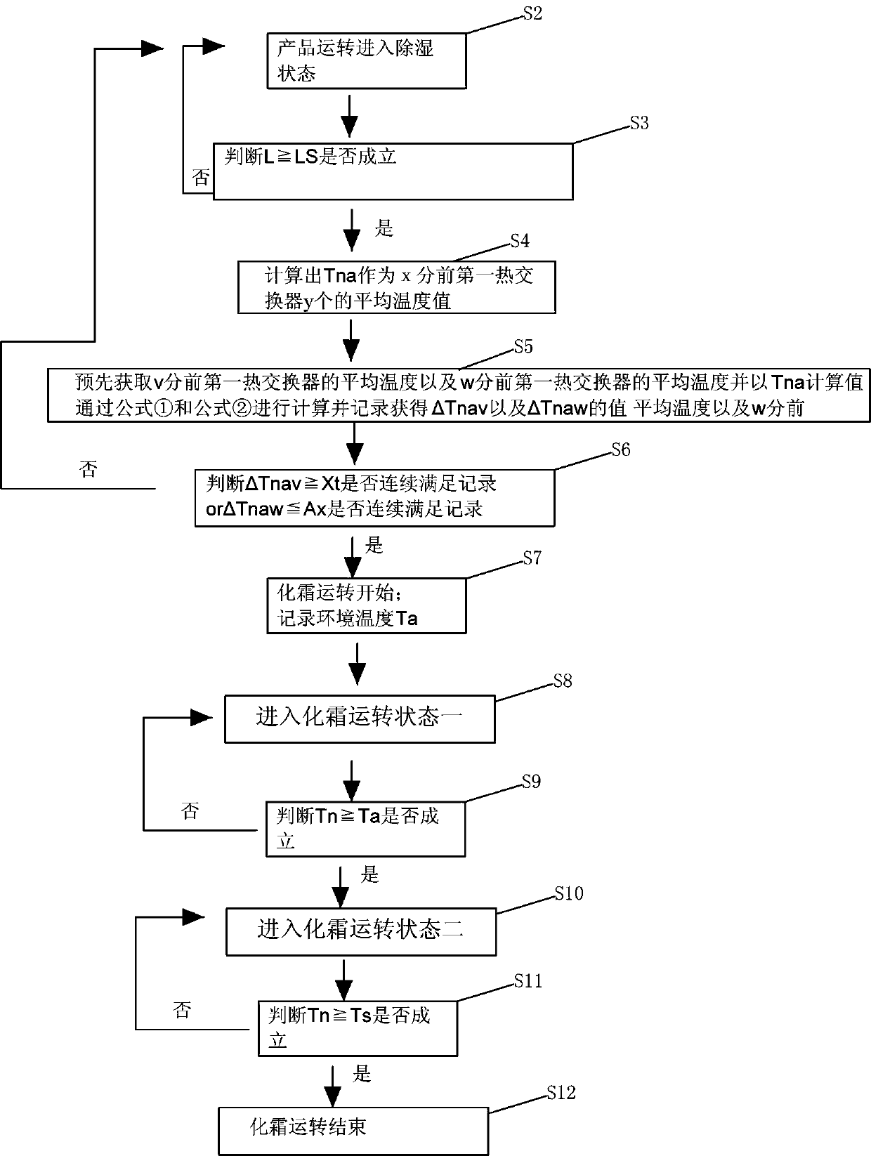
[0034] Such as figure 1 As shown, a defrosting method for a dehumidifier provided in this embodiment includes the following steps:

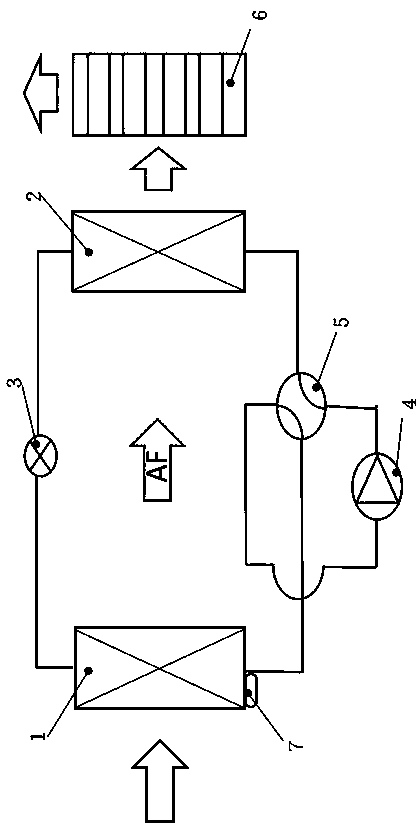
[0035] Step S1, providing a dehumidifier, which includes a first heat exchanger, a second heat exchanger, a compressor, a pressure reducer, a fan, a four-way reversing valve, and a temperature detector installed on the first heat exchanger ;

[0036] Such as figure 2 As shown, in this embodiment, the dehumidifier is equipped with a first heat exchanger 1, a second heat exchanger 2, a compressor 3, a pressure reducer 4, a fan 5, a four-way reversing valve 6 and a The temperature detector 7 on the heat exchanger 1, the fan 5 is located at the rear end of the second heat exchanger 2, the first heat exchanger 1 is located at the front end of the second heat exchanger 2, and the first Both ends of the heat exchanger 1 are respectively connected to the pressure reducer 4 and one end of the four-way reversing valve 6, and the two ends of the second ...


PUM


Abstract

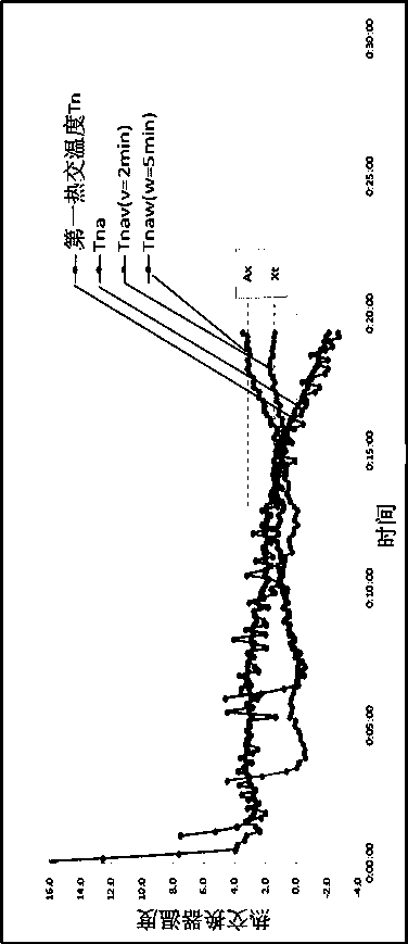
The invention discloses a defrosting method of a dehumidifier. The defrosting method of the dehumidifier comprises the following steps that the temperature condition of a first heat exchanger in a previous period of time is detected in real time and is compared with a preset temperature; then the average temperature of a first heat exchanger before v minutes and the average temperature of the first heat exchanger before w minutes are compared with the average temperature Tna obtained in real time twice, a state that defrosting state is needed is judged as long as one temperature comparison meets a preset requirement, and then defrosting is started, meanwhile, in the defrosting process, a fan is not stopped firstly, and it is guaranteed that the effect that the fan continues supplying air and then the dehumidification is conducted through a second heat exchanger so that the dehumidification effect can be further achieved in the initial defrosting stage.

Description

technical field [0001] The invention relates to the technical field of dehumidifiers, and particularly designs a defrosting method for a dehumidifier. Background technique [0002] Dehumidifiers are also known as dehumidifiers, dryers, and dehumidifiers. They can generally be divided into two categories: civil dehumidifiers and industrial dehumidifiers, and belong to a part of the air-conditioning family. Usually, a conventional dehumidifier consists of a compressor, a heat exchanger, a fan, a water tank, a casing and a controller. [0003] Its working principle is: the humid air is drawn into the machine by the fan, and passes through the heat exchanger. At this time, the water molecules in the air condense into water droplets, and the dried air after treatment is discharged outside the machine. This cycle keeps the indoor humidity at a suitable level. Relative humidity. [0004] Therefore, with the expansion of the scope of use of dehumidifier products, dehumidifiers hav...

Claims


Application Information

Patent Timeline
IPC IPC(8): F24F3/14F24F11/41F24F11/61F24F11/64F25B47/02F24F140/20F24F110/10
CPCF24F3/1405F25B47/02F25B2600/01F24F11/41F24F11/61F24F11/64F24F2110/10F24F2140/20
Inventor 田中丈
Owner 宁波德业日用电器科技有限公司
Learn More