A Drainage System of Generator Large Shaft Air Supplement Pipe

A technology of drainage system and air supply pipe, which is applied in the directions of hydropower generation, engine components, machines/engines, etc., can solve the hidden danger of flooded generator accident and the problem of water leaking from the large shaft air supply pipe, so as to prevent falling, ensure the air supply volume, The effect of improving work efficiency

Active Publication Date: 2021-11-02
张宏杰
View PDF0 Cites 0 Cited by
  • Summary
  • Abstract
  • Description
  • Claims
  • Application Information

AI Technical Summary

Problems solved by technology

When the precipitation level of the reservoir discharges flood and sand during the flood season, the hydro-generator unit needs to be shut down to avoid sand. When the hydro-generator unit is shut down or in the process of starting up, because the draft pipe of the unit is blocked by sediment, there is a phenomenon that the large shaft air supplement pipe leaks water , It is easy to cause hidden dangers of generator accidents caused by flooding

Method used


Image

  • A Drainage System of Generator Large Shaft Air Supplement Pipe
  • A Drainage System of Generator Large Shaft Air Supplement Pipe
  • A Drainage System of Generator Large Shaft Air Supplement Pipe

Examples


Embodiment 1

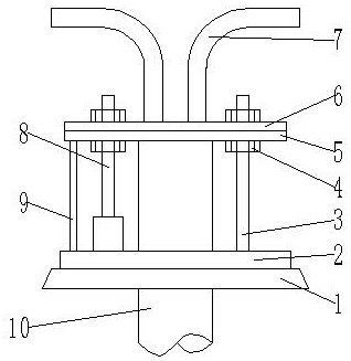
[0045] Such as Figure 1-3 As shown, a drainage system for the large shaft air supply pipe of a generator includes a rotating shaft air supply pipe 10 and a generator cover floor 1; the air inlet of the rotating shaft air supply pipe 10 runs through the generator cover floor 1 and is located on the generator cover floor 1 above; the generator cover floor 1 is provided with an annular support plate 2, and the rotating shaft air supply pipe 10 is located in the round hole of the annular support plate 2; the upper side of the annular support plate 2 is provided with a guide rod 3 and a push-pull rod 8; The upper end of the guide rod 3 and the output shaft of the push-pull rod 8 are connected to the upper pressure plate 6; the upper end of the guide rod 3 and the output shaft of the push-pull rod 8 are connected to the upper pressure plate 6 The connection is provided with a threaded cap 4, and the threaded cap 4 is used to fix the upper platen 6; the upper platen 6 is provided wi...

Embodiment 2

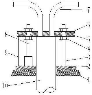
[0053] Such as Figure 4-6 As shown, a drainage system for the large shaft air supply pipe of a generator includes a rotating shaft air supply pipe 10 and a generator cover floor 1; the air inlet of the rotating shaft air supply pipe 10 runs through the generator cover floor 1 and is located on the generator cover floor 1 above; the generator cover floor 1 is provided with an annular support plate 2, and the rotating shaft air supply pipe 10 is located in the round hole of the annular support plate 2; the upper side of the annular support plate 2 is provided with a guide rod 3 and a push-pull rod 8; The upper end of the guide rod 3 and the output shaft of the push-pull rod 8 are connected to the upper pressure plate 6; the upper end of the guide rod 3 and the output shaft of the push-pull rod 8 are connected to the upper pressure plate 6 The connection is provided with a threaded cap 4, and the threaded cap 4 is used to fix the upper platen 6; the upper platen 6 is provided wi...

Embodiment 3

[0066] Different from Embodiments 1 and 2, the distance H between the annular support plate 2 and the sealing plate 5, the length L of the output shaft of the push-pull rod, the diameter R1 of the draft tube, and the diameter R2 of the air supply tube satisfy the following requirements: relation:

[0067] H·R2=α·M·L·R1;

[0068] In the formula: the units of H, L, R1 and R2 are cm;

[0069] M is the number of draft tubes;

[0070] α is the correlation coefficient, and the value range is 5.2-8.4.

[0071] Since it takes a certain amount of time for the sensor to transmit the signal to the processor, when α is less than 5.2, the sealing delay of the rotating shaft air supply pipe 10 is likely to occur, resulting in the phenomenon that the rotating shaft air supply pipe 10 is not sealed yet, and the rotating shaft air supply pipe 10 leaks water. When α is greater than 8.4, it is easy to have a large amount of water coming out of the rotating shaft air supply pipe 10, which lead...


PUM


Abstract

The invention discloses a large shaft air supply pipe drainage system for a generator, which comprises a rotating shaft air supply pipe and a generator cover floor; the air inlet of the rotating shaft air supply pipe runs through the generator cover floor and is located above the generator cover floor; An annular support plate is arranged above the floor of the generator hood; a guide rod and a push-pull rod are arranged on the upper side of the annular support plate; an upper pressure plate is arranged at the air inlet of the rotating shaft; the upper end of the guide rod and the push-pull rod output The shafts are all connected to the upper platen; the upper end of the guide rod and the output shaft of the push-pull rod and the upper platen are connected with threaded caps; the upper platen is provided with a guide tube; the guide tube communicates with the air supply pipe of the rotating shaft. By setting the diversion pipe, the water emerging from the air supply pipe of the rotating shaft is diverted to the leakage drainage collection well, so as to prevent the water from the air supply pipe of the large shaft from entering the top of the generator, and effectively prevent water from entering the top of the generator.

Description

technical field [0001] The invention belongs to the technical field of generator equipment, and in particular relates to a drainage system for a large shaft air supply pipe of a generator. Background technique [0002] A hydroelectric generator is a generator that uses a water turbine as the prime mover to convert water energy into electrical energy. When the water flows through the water turbine, the water energy is converted into mechanical energy, and the rotating shaft of the water turbine drives the rotor of the generator, which converts the mechanical energy into electrical energy and outputs it. It is the main power equipment for generating electric energy in hydropower stations. When the precipitation level of the reservoir discharges flood and sand during the flood season, the hydro-generator unit needs to be shut down to avoid sand. When the hydro-generator unit is shut down or in the process of starting up, because the draft pipe of the unit is blocked by sedimen...

Claims


Application Information

Patent Timeline
Patent Type & Authority Patents(China)
IPC IPC(8): F03B11/04F03B11/00
CPCF03B11/002F03B11/006F03B11/008F03B11/04Y02E10/20
Inventor 张宏杰张再虎潘淑改许天阳游建京李锐刘宇明鲁锋任涛马畅许守能
Owner 张宏杰
Why Eureka
Try Eureka