Compressed air heat exchange system

A heat exchange system and compressed air technology, applied in compressors, compressors with reversible cycles, lighting and heating equipment, etc., can solve the problems of inability to realize humidification function, environmental hazards, etc., and achieve simple structure and reduce the environment Hazardous, good stability

Pending Publication Date: 2020-06-19
GD MIDEA AIR-CONDITIONING EQUIP CO LTD
View PDF7 Cites 1 Cited by
  • Summary
  • Abstract
  • Description
  • Claims
  • Application Information

AI Technical Summary

Problems solved by technology

[0002] In the related art, the heat exchange system with cooling and / or heating function can usually only perform dehumidification operation, but cannot realize the humidification function. In addition, the refrigerant used in the above heat exchange system is harmful to the environment, such as the greenhouse effect, the ozone layer hollow

Method used


Image

  • Compressed air heat exchange system
  • Compressed air heat exchange system
  • Compressed air heat exchange system

Examples


Embodiment 1

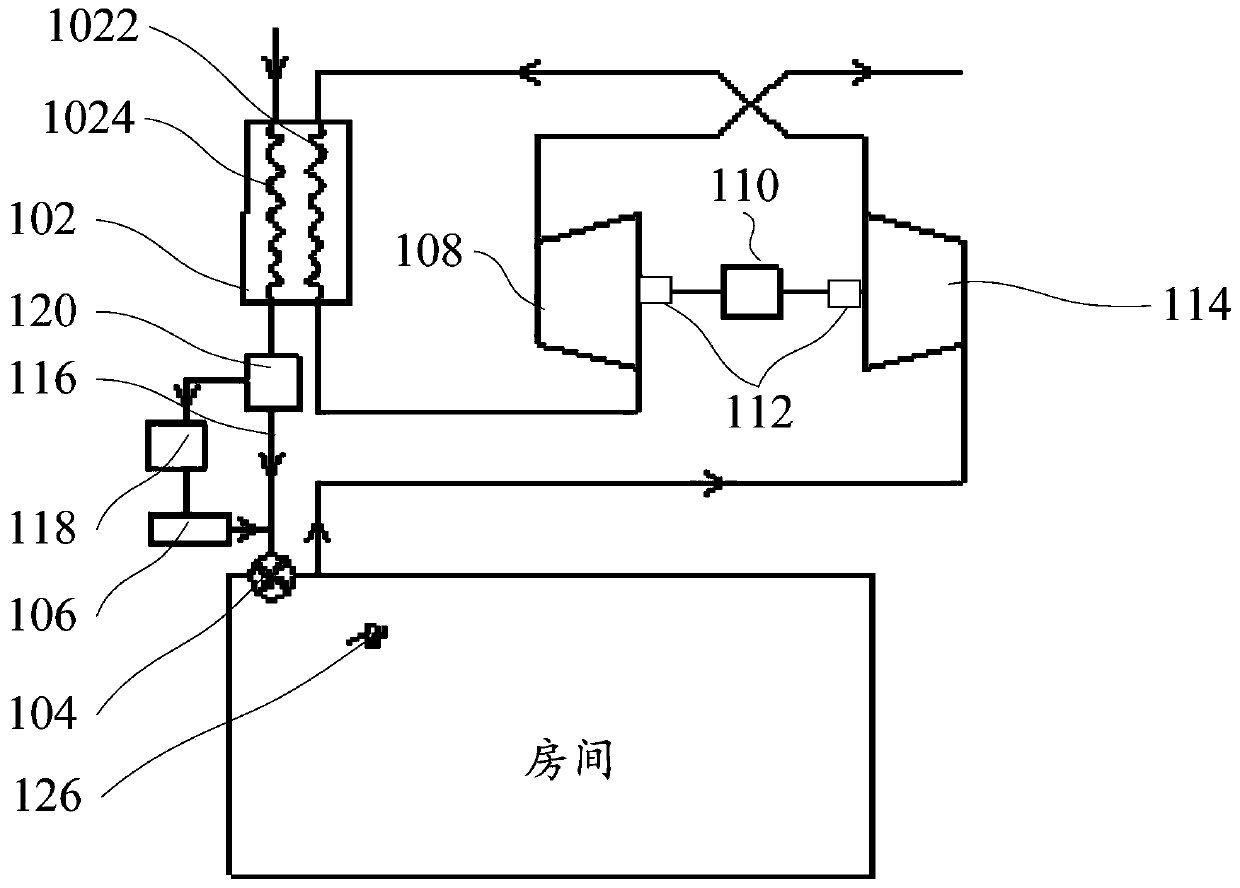
[0053] Such as figure 1 As shown, the compressed air heat exchange system includes: processor (see Figure 6 ), pressurized expansion assembly, heat exchanger 102, fan 104 and humidification module 106.

[0054] Among them, the processor is used to execute computer instructions.

[0055] The heat exchanger 102 is an air-cooled heat exchanger 102, at least including a first flow path 1022 and a second flow path 1024 capable of mutual heat exchange.

[0056] The fan 104 is electrically connected to the processor, and is used to drive outdoor fresh air to flow into the room through the second flow path 1024 .

[0057] The pressurized expansion assembly, the pressurized expansion assembly, is electrically connected to the processor and communicated with the first flow path 1022, and the pressurized expansion assembly is provided with an air return port and an exhaust port.

[0058] The humidification module 106 is electrically connected to the processor, and can communicate wit...

Embodiment 2

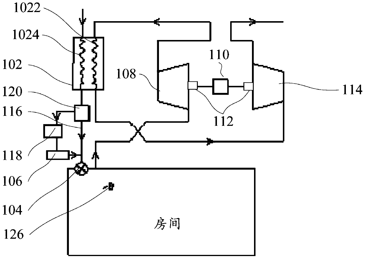
[0071] According to the compressed air heat exchange system of this embodiment, based on different pipeline connection modes, it may only have the functions of heating and humidification.

[0072] Such as figure 2 As shown, in some embodiments, a specific arrangement of the pressurized expansion assembly includes: the expander 108 is provided with an exhaust port and communicated with the outlet of the first flow path 1022, and the compressor 114 is provided with a return air port and connected with the first flow path The inlet of the first flow path 1022 is connected, wherein the indoor air enters the compressor 114 through the air return port to heat up, enters the first flow path 1022 and exchanges heat with the second flow path 1024, and then returns to the expander 108, and the outdoor fresh air in the second flow path 1024 After the temperature rises, it is humidified by the humidification module 106 and enters the room.

[0073] In this embodiment, the air return por...

Embodiment 3

[0075] According to the compressed air heat exchange system of this embodiment, based on different pipeline connection modes, it may only have the functions of cooling and humidification.

[0076] Such as figure 1 As shown, in some embodiments, another specific arrangement of the pressurized expansion assembly, the compressor 114 is provided with an exhaust port, and communicated with the outlet of the first flow path 1022, and the expander 108 is provided with a return air port, and connected with the first flow path The inlet of the path 1022 is connected, wherein the indoor air enters the expander 108 through the air return port to cool down, enters the first flow path 1022 and exchanges heat with the second flow path 1024, and then returns to the compressor 114, and the outdoor fresh air in the second flow path 1024 cools down. Afterwards, it is humidified by the humidification module 106 and enters the room.

[0077]In this embodiment, the air return port is connected to...


PUM


Abstract

The invention provides a compressed air heat exchange system. The compressed air heat exchange system comprises a processor, a heat exchanger, a fan, a pressure-increased expansion assembly and a humidification module, wherein the heat exchanger comprises a first flow path and a second flow path, and the first flow path and the second flow path are arranged in parallel; the fan is electrically connected with the processor and used for driving outdoor fresh air to flow into a room through the second flow path; the pressure-increased expansion assembly is electrically connected with the processor and communicates with the first flow path, and an air return inlet and an air outlet are formed in the pressure-increased expansion assembly; the humidification module is electrically connected withthe processor and capable of being in communication with an outlet of the second flow path; and the processor is further used for executing computer instructions to perform the following steps of controlling the operation of the humidification module and the fan to introduce the humidified outdoor fresh air into the room. By the technical scheme, air is directly used as a refrigerant to replace compound refrigerants used in the related technology so as to achieve the effect of humidifying the room and reduce the harm to the environment.

Description

technical field [0001] The present application relates to the field of household operation control, in particular, to a compressed air heat exchange system. Background technique [0002] In the related art, the heat exchange system with cooling and / or heating function can usually only perform dehumidification operation, but cannot realize the humidification function. In addition, the refrigerant used in the above heat exchange system is harmful to the environment, such as the greenhouse effect, the ozone layer hollow. Contents of the invention [0003] This application aims to solve at least one of the technical problems existing in the prior art or related art. [0004] For this reason, the purpose of this application is to propose a new compressed air heat exchange system. [0005] In order to achieve at least one of the above objectives, a compressed air heat exchange system is proposed, which specifically includes: a processor; a heat exchanger, including a first flo...

Claims


Application Information

Patent Timeline
Patent Type & Authority Applications(China)
IPC IPC(8): F25B9/06F25B13/00F25B49/02F25B41/00F25B41/04F25B41/20F25B41/40
CPCF25B9/06F25B13/00F25B49/02F25B41/00F25B2313/02742F25B41/20
Inventor 赵帅白崇俨魏留柱袁紫琪朱兴丹
Owner GD MIDEA AIR-CONDITIONING EQUIP CO LTD
Why Eureka
Try Eureka