A double-row microchannel heat exchanger and its working method

A micro-channel heat exchanger, refrigerant channel technology, applied in the direction of heat exchanger shell, heat exchange equipment, lighting and heating equipment, etc., can solve the problem of poor heat exchange capacity, refrigerant temperature and flow are not controlled, rear row Problems such as poor heat exchange performance of microchannel heat exchangers, to achieve the effect of improving heat exchange performance, improving heat exchange performance, and strong heat exchange capacity

Active Publication Date: 2021-01-15
XI AN JIAOTONG UNIV
View PDF6 Cites 0 Cited by
  • Summary
  • Abstract
  • Description
  • Claims
  • Application Information

AI Technical Summary

Problems solved by technology

[0003] For conventional double-row micro-channel heat exchangers, the flow path of the refrigerant is from the front row of micro-channel heat exchangers to the rear row of micro-channel heat exchangers, or from the rear row of micro-channel heat exchangers to the front row of micro-channel heat exchangers , the refrigerant temperature and flow rate of the front and rear rows of microchannel heat exchangers are not controlled, which generally leads to poor heat transfer performance of the rear row of microchannel heat exchangers, and under frosting conditions, the front row of microchannel heat exchangers The heat exchanger is very easy to frost, which leads to a sharp deterioration of the heat exchange performance of the rear micro-channel heat exchanger; when the double-row micro-channel heat exchanger is used as an evaporator or condenser, the micro-channel heat exchanger will generate gas during the heat exchange process , liquid, if the gas and liquid are not drawn out, the heat exchange capacity of the second half of the microchannel heat exchanger will be poor

Method used


Image

  • A double-row microchannel heat exchanger and its working method
  • A double-row microchannel heat exchanger and its working method
  • A double-row microchannel heat exchanger and its working method

Examples


Embodiment Construction

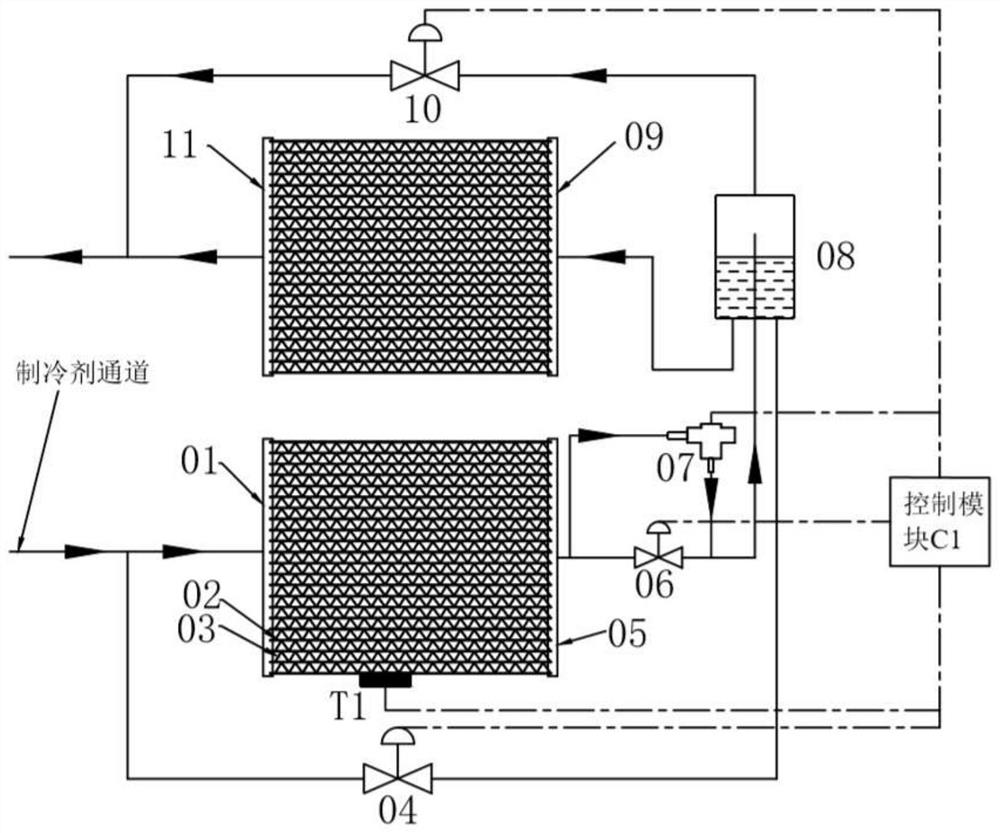
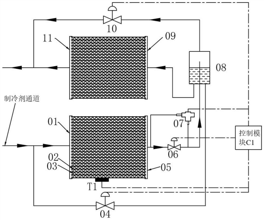
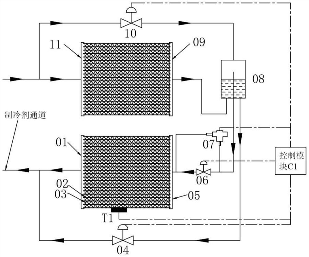
[0021] The specific implementation manners of the present invention will be described in detail below in conjunction with the accompanying drawings.

[0022] Such as figure 1 , figure 2 and image 3 As shown, a double-row microchannel heat exchanger according to the present invention includes a first header 01, a second header 05, a third header 09 and a fourth header 11, which are arranged on the first The liquid collection pipe 01 and the second liquid collection pipe 05, the third liquid collection pipe 09 and the fourth liquid collection pipe 11 are in communication with the first liquid collection pipe 01 and the second liquid collection pipe 05, the third liquid collection pipe 09 and the fourth liquid collection pipe A plurality of flat tubes 02 of the four collecting tubes 11, fins 03 installed between adjacent flat tubes, the first collecting tube 01, the second collecting tube 05, flat tubes 02 and fins 03 constitute the front row of microchannels Heat exchanger,...


PUM


Abstract

The invention discloses a double-row microchannel heat exchanger and a working method thereof. The double-row microchannel heat exchanger comprises four liquid collecting tubes, flat tubes, fins, three ball valves, an electromagnetic expansion valve and a gas-liquid separator. When the double-row microchannel heat exchanger is used as an evaporator and works under the frosting condition, a refrigerant coming out of a front-row microchannel heat exchanger is throttled, so that the double-row microchannel heat exchanger can frost evenly; when the double-row microchannel heat exchanger works under the non-frosting condition, the refrigerant does not pass through the electromagnetic expansion valve; when the double-row microchannel heat exchanger is used as a condenser, the flow of the refrigerant entering the front-row microchannel heat exchanger is increased through adjustment of the opening degrees of the ball valves; the gas-liquid separator is mounted between the front-row microchannel heat exchanger and a back-row microchannel heat exchanger, the gas and the liquid which are produced by the double-row microchannel heat exchanger used as the evaporator and the condenser can be connected in a bypass manner, and thus the performance of the second half of the microchannel heat exchanger can be improved.

Description

technical field [0001] The invention relates to the technical field of double-row micro-channel heat exchangers, in particular to a double-row micro-channel heat exchanger and a working method thereof. Background technique [0002] In the context of energy consumption and air pollution, heat pump systems with high energy efficiency have received more and more attention. As a key component of heat pump systems, heat exchangers play a key role in improving the energy efficiency of the system. Microchannel heat exchangers with small size, compact structure, small refrigerant charge and low production cost have great advantages and can be used in heat pump systems instead of finned tube heat exchangers. [0003] For conventional double-row micro-channel heat exchangers, the flow path of the refrigerant is from the front row of micro-channel heat exchangers to the rear row of micro-channel heat exchangers, or from the rear row of micro-channel heat exchangers to the front row of ...

Claims


Application Information

Patent Timeline
Patent Type & Authority Patents(China)
IPC IPC(8): F25B39/02F25B39/04F28F9/00F28F17/00
CPCF25B39/02F25B39/04F28F9/00F28F17/005
Inventor 熊通晏刚樊超超鱼剑琳
Owner XI AN JIAOTONG UNIV
Why Eureka
Try Eureka