Optical fiber connector plug, optical fiber adapter and optical fiber connector
A fiber optic connector and fiber optic adapter technology, which is applied in the direction of light guides, optics, instruments, etc., can solve the problems of low coupling efficiency of optical signals, achieve the effects of improving coupling efficiency, improving docking effect, and preventing shaking
- Summary
- Abstract
- Description
- Claims
- Application Information
AI Technical Summary
Problems solved by technology
Method used
Image
Examples
Embodiment 1
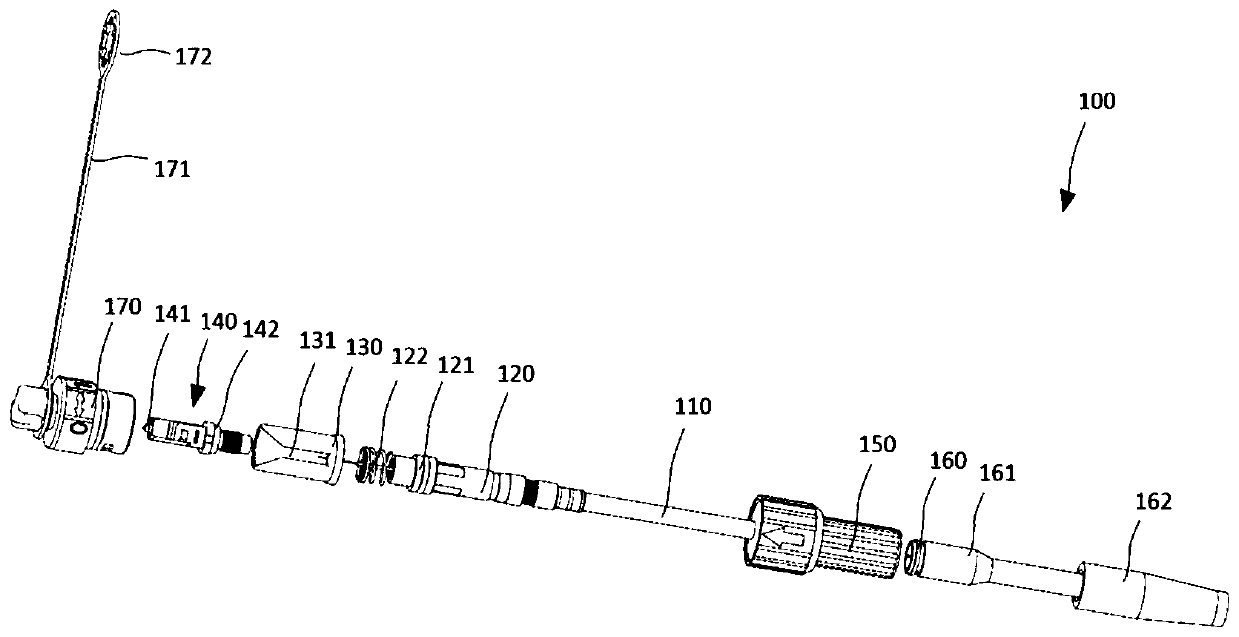
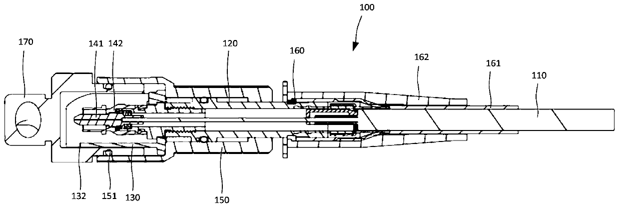
[0051] like figure 1 and figure 2 As shown, the fiber optic connector plug 100 provided by Embodiment 1 of the present application includes an optical fiber 110 or an optical cable containing an optical fiber, a ferrule assembly 140, a connector 120 and a guide cylinder 130, wherein the ferrule assembly 140 includes a ferrule 141, and the ferrule assembly 140 includes a ferrule 141, and the ferrule The core 141 is fixedly connected to the optical fiber 110, the connector 120 is sleeved on the optical fiber 110 and fixedly connected to the rear end of the ferrule 141, and the guide cylinder 130 is sleeved on the connector 120 and arranged around the ferrule 141; when two optical fibers are connected When the connector plug 100 is inserted into the fiber optic adapter 200 so that the front ends of the two ferrules 141 are in the docking state, the front ends of the ferrule 141 protrude from the front end of the guide cylinder 130 .
[0052] The connector 120 is sheathed on the...
Embodiment 2
[0076] see image 3 and Figure 4 , Embodiment 2 of the present application provides another optical fiber connector plug 100, the optical fiber connector plug 100 includes an optical fiber 110, a ferrule assembly 140, a connector 120 and a guide cylinder 130, wherein the ferrule assembly 140 is fixed to the optical fiber 110 connection, the connector 120 is sleeved on the optical fiber 110 and fixedly connected to the rear end of the ferrule assembly 140, the guide cylinder 130 is sleeved on the connector 120 and arranged around the ferrule assembly 140; the optical fiber connector plug provided in this embodiment When the 100 is in the non-docking state and the docking state, the front end of the ferrule assembly 140 protrudes from the front end of the guide cylinder 130 .
[0077] In the optical fiber connector plug 100 provided in the embodiment of the present application, the structure of the optical fiber 110 and the ferrule assembly 140, the connection mode or cooperat...
Embodiment 3
[0082] like Figure 5 and Image 6 As shown, the fiber optic adapter 200 provided by the embodiment of the present application includes a flange 210 and a ferrule butt joint sleeve 240, wherein the outline of the flange 210 can be a cylindrical structure, and the flange 210 has a first end 214 and a second end 224. Along the direction from the first end 214 to the second end 224, the middle part of the flange 210 is provided with a first cavity 211, a sleeve housing cavity 230 and a second cavity 221 in sequence, wherein the first cavity 211 is used to accommodate The ferrule assembly 140 (including ferrule 141 and frame cover 142) of a fiber optic connector plug 100, the first cavity 211 is used to accommodate the ferrule assembly 140 (comprising ferrule 141 and frame cover) of another optical fiber connector plug 100 142 ), the sleeve accommodating cavity 230 is used for accommodating the ferrule butt sleeve 240 .
[0083] The entrance of the first cavity 211 is formed at...
PUM
| Property | Measurement | Unit |
|---|---|---|
| length | aaaaa | aaaaa |
Abstract
Description
Claims
Application Information
 - R&D
- Intellectual Property
- Life Sciences
- Materials
- Tech Scout
- Unparalleled Data Quality
- Higher Quality Content
- 60% Fewer Hallucinations
Browse by: Latest US Patents, China's latest patents, Technical Efficacy Thesaurus, Application Domain, Technology Topic, Popular Technical Reports.
© 2025 PatSnap. All rights reserved.Legal|Privacy policy|Modern Slavery Act Transparency Statement|Sitemap|About US| Contact US: help@patsnap.com


