Electronic switch and method for increasing current flux and preventing contacts from heating and burning

A flux-enhancing, electronic switch technology, applied in electrical switches, contact heating/cooling, contact driving mechanisms, etc., can solve the problems of smaller block contact area, contact heating and burning, heating and burning, etc. , achieve the effect of preventing the contact from heating up and burning, which is conducive to radiation heat dissipation

Active Publication Date: 2021-02-02
深圳市卡贝电子技术有限公司
View PDF6 Cites 0 Cited by
  • Summary
  • Abstract
  • Description
  • Claims
  • Application Information

AI Technical Summary

Problems solved by technology

[0005] The main purpose of the present invention is to provide an electronic switch that increases the current flux to prevent the contact from heating and burning, and solves the problem of contact heating and burning when the current flux increases through the structural design of the contact shape change, or Applicable to electronic switch fields requiring large current flux, such as automobiles, motorcycles, ships, tanks, etc.
[0006] The second main purpose of the present invention is to provide a method of increasing the current flux to prevent the contacts from heating and burning, which is used to solve the problem of block shape due to the increase of the current flux when the two electrodes are energized. The problem of heat generation and burnout due to the reduction of the contact area
[0007] The third main invention objective of the present invention is to provide a manufacturing method for increasing the current flux to prevent the contact from heating and burning, which can manufacture an electronic switch that provides a ring-shaped electrical contact area, and solve the problem of contact heating and burning when the current flux increases

Method used


Image

  • Electronic switch and method for increasing current flux and preventing contacts from heating and burning
  • Electronic switch and method for increasing current flux and preventing contacts from heating and burning
  • Electronic switch and method for increasing current flux and preventing contacts from heating and burning

Examples


Embodiment Construction

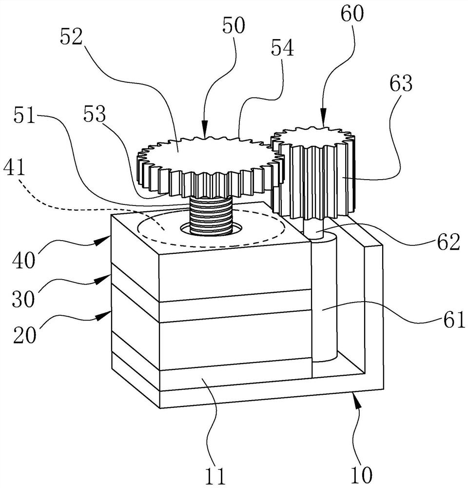
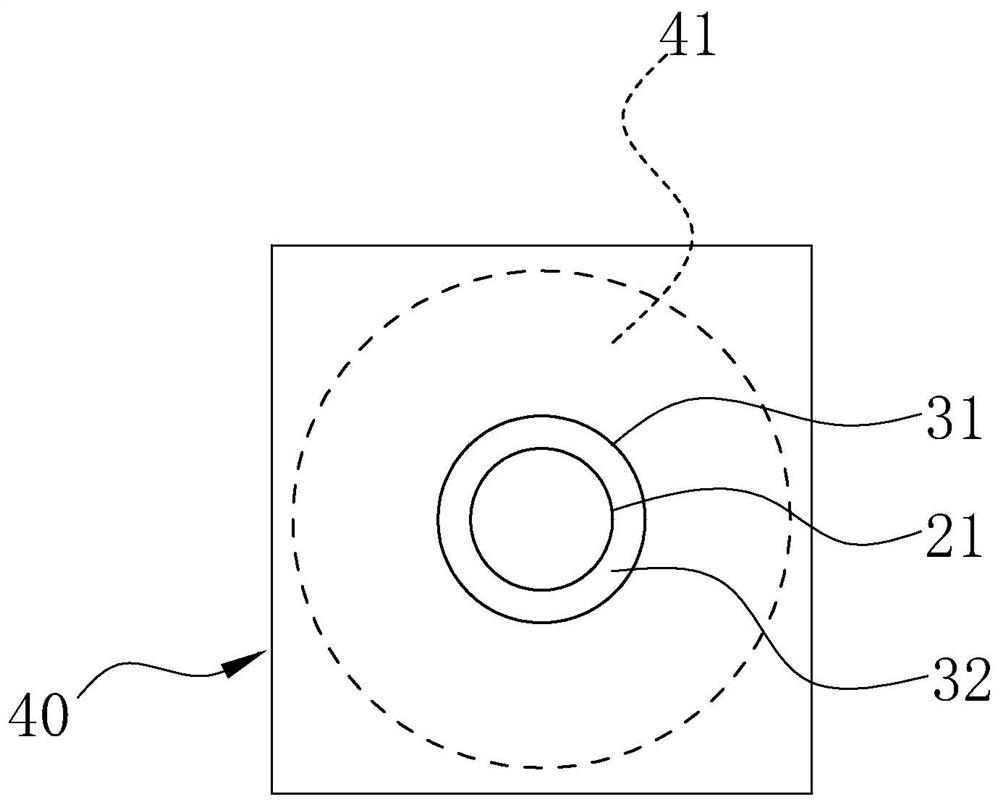
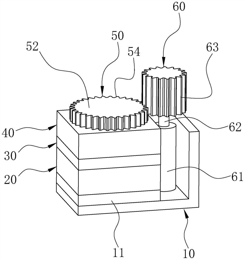
[0054] The following will clearly and completely describe the technical solutions in the embodiments of the present invention with reference to the accompanying drawings in the embodiments of the present invention. Obviously, the described embodiments are only part of the embodiments of the present invention, not all of them. Based on the embodiments of the present invention, other embodiments obtained by persons of ordinary skill in the art on the premise of understanding the inventive concepts of the present invention all fall within the protection scope of the present invention.

[0055] It should be noted that if there is a directional indication (such as up, down, left, right, front, back...) in the embodiment of the present invention, the directional indication is only used to explain the position in a certain posture (as shown in the accompanying drawing). If the specific posture changes, the directional indication will also change accordingly.

[0056] In order to faci...


PUM


Abstract

The invention relates to an electronic switch and a method for increasing the current flux and preventing contacts from heating and burning. The electronic switch includes two electrode layers arranged in parallel up and down, an insulating layer between the two electrode layers and a lifting extension piece, an upper electrode layer and an insulating layer A movable through hole is opened through, and the movable through hole is insulated in the upper electrode layer; the lifting extension is arranged to align with the movable through hole and electrically connected to the lower electrode layer, and the lifting extension has a guide rod that can move in the movable through hole and The contact head connected to the top of the guide rod, the contact head faces the bottom of the guide rod to form a ring surface that is in electrical contact with the upper electrode layer, and the driving device is used to sink the lifting extension to engage with the upper electrode layer, and the ring surface is connected to the upper electrode layer The outer surface of the layer forms a ring-shaped electrical contact area around the active via, thereby solving the problem of contact heating and burning when the current flux increases.

Description

technical field [0001] The invention relates to an electronic switch for supplying current, in particular to an electronic switch and a method for increasing the current flux and preventing contacts from heating and burning. Background technique [0002] As an on-off device for power supply or signal transmission, the power-off switch can be divided into manual passive switch and programmable electronic switch. The size of the electronic switch can be further reduced and program monitoring can be realized. The existing electronic switches with large current flux generally use Darlington tubes, field sensors or relays. Darlington tubes and field switches are good for close control, but because of chip design, they cannot The power-off isolation effect is poor, and its product stability and reliability are not as good as relays. Although the relay can achieve power-off isolation, the contact area of ​​the two electrodes with elastic clips is uncontrollable and easy to age wh...

Claims


Application Information

Patent Timeline
Patent Type & Authority Patents(China)
IPC IPC(8): H01H1/06H01H1/62H01H3/26H01H3/40H01H11/00H01H11/04
CPCH01H1/06H01H1/62H01H3/26H01H3/40H01H11/00H01H11/04
Inventor 谢宗营毕涵
Owner 深圳市卡贝电子技术有限公司
Why Eureka
Try Eureka