
Novel box-type substation heat dissipation device with self-contained power supply

A technology of box-type substation and self-contained power supply, which is applied in substation/distribution device shell, substation/switchgear cooling/ventilation, substation/switch layout details, etc., which can solve the problem of poor heat dissipation effect, affecting heat dissipation effect, and equipment operation Disadvantages and other problems, to achieve high heat dissipation efficiency, to ensure the effect of heat dissipation

Active Publication Date: 2020-06-19
扬州乐军电子科技有限公司
View PDF12 Cites 0 Cited by
  • Summary
  • Abstract
  • Description
  • Claims
  • Application Information

AI Technical Summary

Problems solved by technology

In hot and humid areas, especially in the Yangtze River Basin, the temperature is high and the humidity is high in summer. If the cooling device of the substation with this structure is used, the temperature of the equipment in the substation will be high. Transformer service life
[0003] The heat dissipation mechanism provided in this technical solution is only equipped with a heat conduction plate for heat transfer and heat dissipation, but it can only dissipate the heat on the rear side wall of the transformer, and the heat dissipation effect is poor; The heat formed cannot be discharged in time, which affects the final heat dissipation effect

Method used


Image

  • Novel box-type substation heat dissipation device with self-contained power supply
  • Novel box-type substation heat dissipation device with self-contained power supply
  • Novel box-type substation heat dissipation device with self-contained power supply

Examples


Embodiment Construction

[0026] In order to make the technical means, creative features, goals and effects achieved by the present invention easy to understand, the present invention will be further described below in conjunction with specific embodiments.

[0027] In describing the present invention, it should be understood that the terms "upper", "lower", "front", "rear", "left", "right", "top", "bottom", "inner", " The orientation or positional relationship indicated by "outside", etc. is based on the orientation or positional relationship shown in the drawings, and is only for the convenience of describing the present invention and simplifying the description, rather than indicating or implying that the referred device or element must have a specific orientation, so as to Specific orientation configuration and operation, therefore can not be construed as limiting the present invention; in the description of the present invention, it should be noted that, unless otherwise clearly specified and limit...


PUM


Abstract

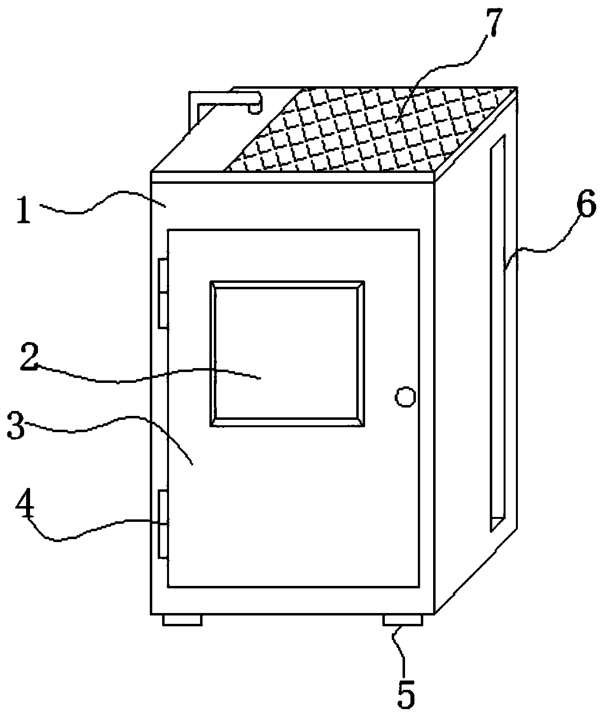
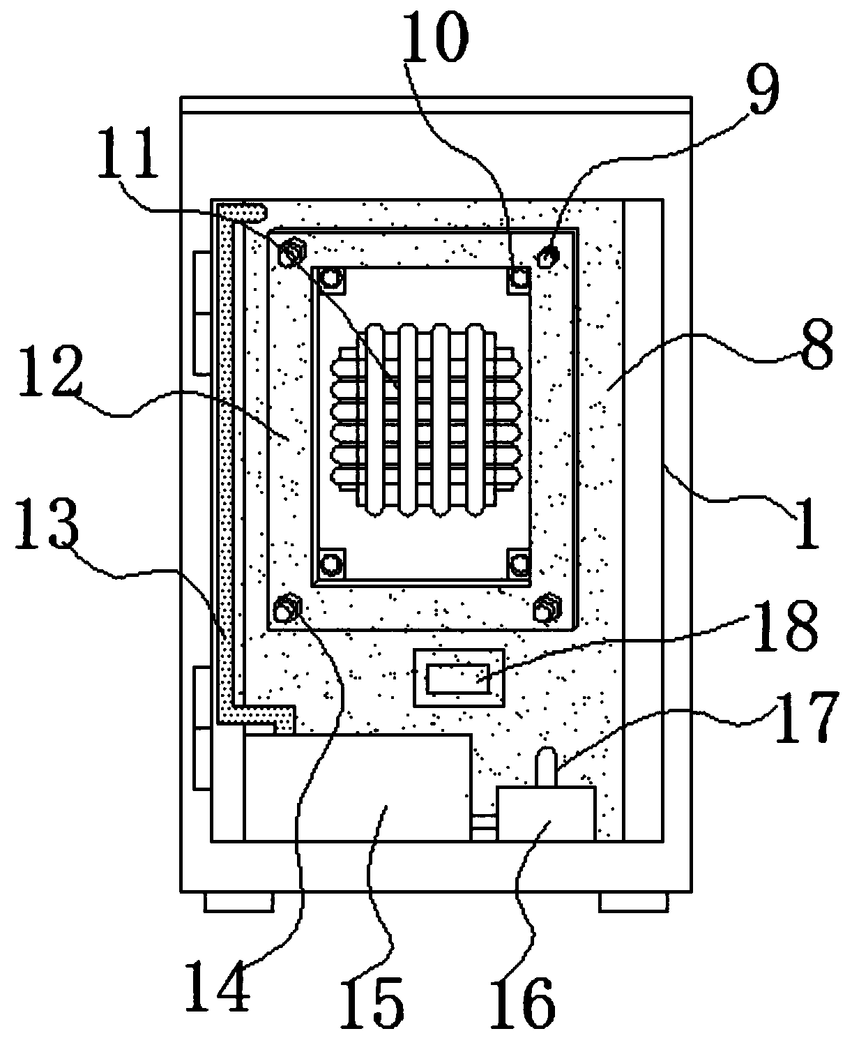
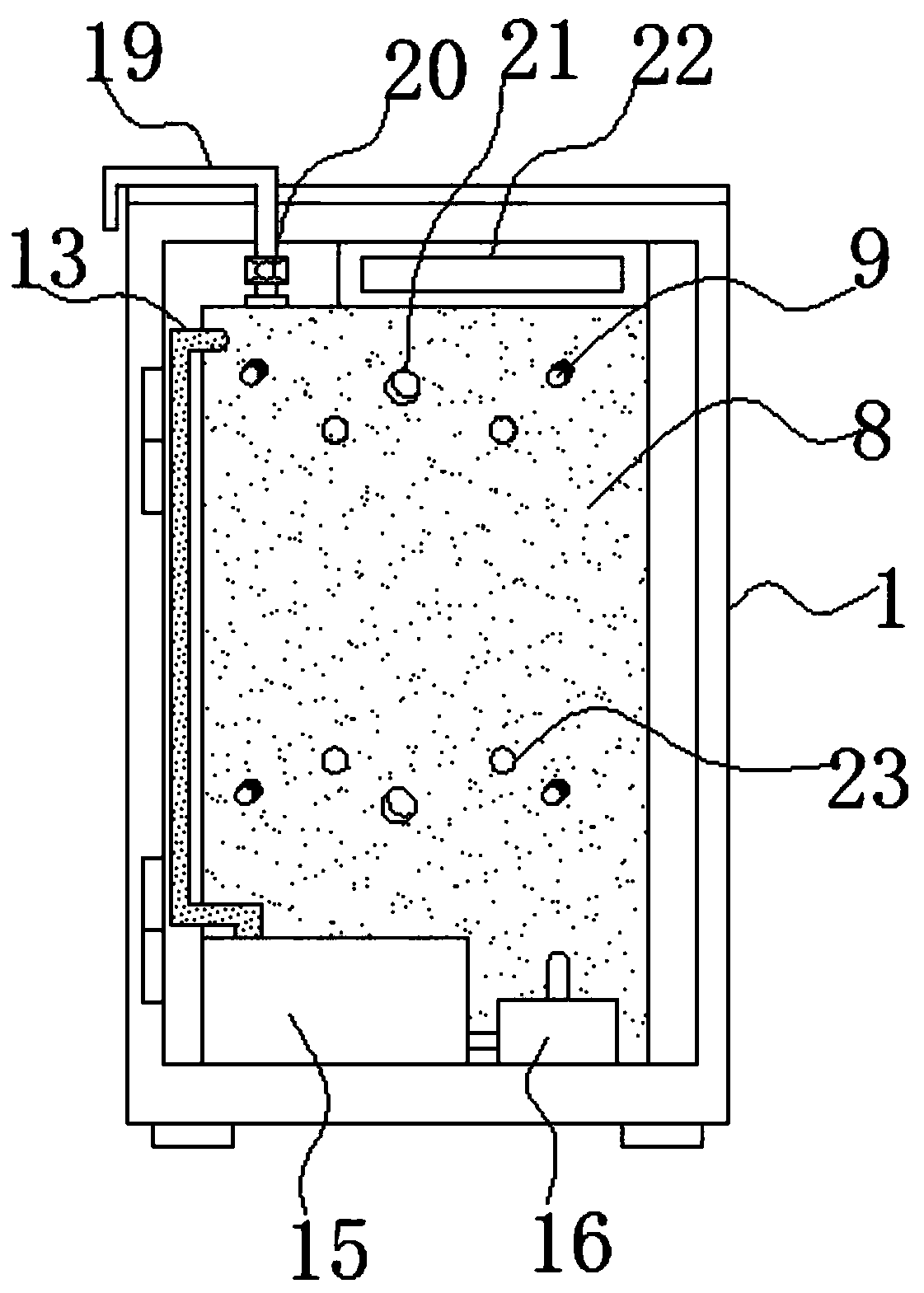
The invention relates to the technical field of self-contained power supply heat dissipation and discloses a novel box-type substation heat dissipation device with a self-contained power supply. The device comprises a cabinet, rubber bases are fixedly connected to four corners of the bottom of the cabinet, and a solar photovoltaic panel is fixedly connected to the top of the cabinet; and a rear side of an inner cavity of the cabinet is fixedly connected with a heat dissipation aluminum box vertically upwards. According to the device, two butt-joint communicating pipes on a rear side of a concentric-square-shaped cooling aluminum box are inserted into butt-joint holes of the cooling aluminum box in a sealed mode, a suction pump works in the later period to suck oil in an oil tank into the cooling aluminum box and enable the oil to enter the concentric-square-shaped cooling aluminum box through the butt-joint holes, the heat of a transformer is fully cooled in an omnibearing mode, and the cooling efficiency is higher; when much hot air exists in the heat dissipation aluminum box, the hot air is exhausted through a one-way valve and an air escape valve, and the situation that heat cannot be dissipated inside is avoided; and meanwhile, four groups of draft fans work to fully pump and discharge heat on heat dissipation fins such that the heat dissipation effect is ensured.

Description

technical field [0001] The invention relates to the technical field of self-contained power supply heat dissipation, in particular to a novel box-type substation heat dissipation device with self-contained power supply. Background technique [0002] At present, the medium and low voltage cabinets of existing box-type substations are generally located on opposite sides of the transformer, and the transformer can only be equipped with heat dissipation devices on the other two sides, that is, double-sided heat dissipation. In addition, there is no other auxiliary heat dissipation structure. In hot and humid areas, especially in the Yangtze River Basin, the temperature is high and the humidity is high in summer. If the cooling device of the substation with this structure is used, the temperature of the equipment in the substation will be high. The service life of the transformer. [0003] The heat dissipation mechanism provided in this technical solution is only equipped with a...

Claims


Application Information

Patent Timeline
IPC IPC(8): H02B1/56H02B1/30
CPCH02B1/30H02B1/565
Inventor 张龙蔡秀东周坤
Owner 扬州乐军电子科技有限公司
Learn More