
A Current Sharing Method Combining Preset Bias Angle and Shared Synchronization Signal

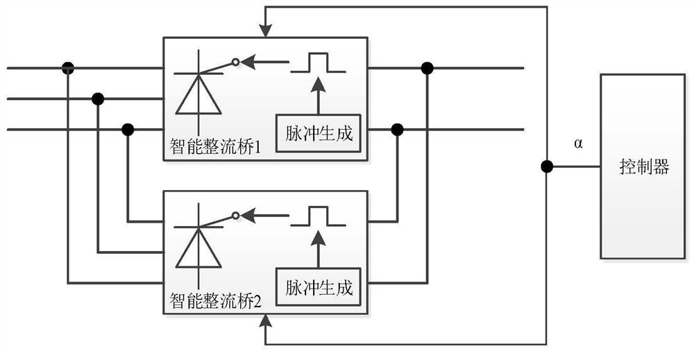
A technology of synchronization signal and bias angle, which is applied in the output power conversion device, the conversion of AC power input to DC power output, electrical components, etc., can solve the problem of not considering hardware differences, etc. The effect of small perturbations

Active Publication Date: 2021-03-26
THREE GORGES NENGSHIDA ELECTRIC
View PDF5 Cites 0 Cited by
  • Summary
  • Abstract
  • Description
  • Claims
  • Application Information

AI Technical Summary

Problems solved by technology

[0009] But this scheme does not take into account the differences in hardware
Although each smart rectifier bridge uses the same synchronous shaping circuit, due to the dispersion of component parameters, the phase deviation that each smart rectifier bridge needs to compensate is still slightly different, and this difference must be compensated in the current sharing control

Method used


Image

  • A Current Sharing Method Combining Preset Bias Angle and Shared Synchronization Signal
  • A Current Sharing Method Combining Preset Bias Angle and Shared Synchronization Signal
  • A Current Sharing Method Combining Preset Bias Angle and Shared Synchronization Signal

Examples


Embodiment

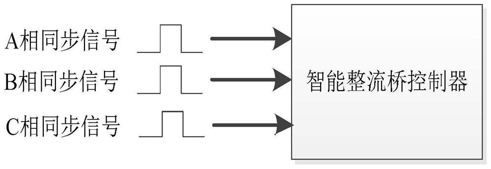
[0043] Such as Figure 1-Figure 7 As shown, the present invention uses the same hardware as the patent application No. 201910223958.X, and shares the synchronization information and synchronization bias angle of all parallel smart rectifier bridges through the communication network.

[0044] Determine the synchronous bias angle for each smart rectifier bridge through a small current test: only one smart rectifier bridge operates at a time, and use the phase A of this rectifier bridge to synchronously drive the trigger pulse. The anode voltage is set above 80V, and the small current tests of all smart rectifier bridges use the same amplitude anode voltage. At this time, the phase shift of the synchronous shaping circuit due to the startup threshold is basically the same as the phase shift during normal operation. Adjust the synchronous bias angle of smart rectifier bridge 1 so that the output waveform at 60° is consistent with the theory, and record the output voltage at this t...


PUM


Abstract

The present invention provides a current sharing method that combines a preset bias angle with a shared synchronization signal. Each intelligent rectifier bridge determines its own synchronization bias angle through a small current test; it shares local data with all parallel intelligent rectifier bridges through a communication network. The accessed synchronization signal and synchronization offset angle; when using the synchronization signal of other intelligent rectifier bridges as the driving signal of the trigger pulse, the synchronization offset angle of the intelligent rectifier bridge where the synchronization signal source is located is used as the synchronization offset angle of the trigger pulse; Each smart rectifier bridge adjusts its own current-sharing bias angle through high-current tests to obtain the current-sharing bias angles of all smart rectifier bridges; each smart rectifier bridge improves the performance of each smart rectifier bridge under typical operating conditions by superimposing the current-sharing bias angle. Current sharing characteristics under. The present invention ensures the consistency of the synchronization signals of each intelligent rectifier bridge by sharing synchronization signals and synchronization bias angles, and then improves the current sharing characteristics of each intelligent rectifier bridge under typical working conditions by superimposing fixed current-sharing bias angles.

Description

technical field [0001] The invention relates to the field of high-power electric electronics, in particular to a current sharing method combining a preset bias angle with a shared synchronous signal. Background technique [0002] High-power power electronic devices usually need to use multiple thyristor three-phase rectifier bridges to output in parallel. Smart rectifier bridge solutions such as figure 1 As shown, the controller outputs the trigger angle to the smart rectifier bridge through the communication network, and the smart rectifier bridge controller generates a control pulse to trigger the rectifier bridge according to the synchronization signal and the trigger angle, and converts the three-phase AC power supply on the anode side into a DC power supply. [0003] Due to hardware differences in many aspects such as the conduction characteristics of the thyristor and the internal resistance of the bridge arm of the smart rectifier bridge, the output currents of the sm...

Claims


Application Information

Patent Timeline
Patent Type & Authority Patents(China)
IPC IPC(8): H02M7/162
CPCH02M7/162
Inventor 余翔赵先元马小高刘钰琦高向鹏
Owner THREE GORGES NENGSHIDA ELECTRIC
Learn More