An iron sheet fixed-distance slotter for building an iron sheet shed

A technology of iron sheet and fixed distance, which is applied in the direction of manufacturing tools, driving devices, metal processing machinery parts, etc., can solve the problems of low work efficiency and troublesome operation, and achieve the effect of high work efficiency and convenient operation

Active Publication Date: 2021-07-16
吴艳美
View PDF7 Cites 0 Cited by
  • Summary
  • Abstract
  • Description
  • Claims
  • Application Information

AI Technical Summary

Problems solved by technology

[0005] In order to overcome the disadvantages of measuring the cutting position with a measuring ruler, and then marking it, after marking, people use a cutting tool to cut and slit the iron sheet. This operation is troublesome and causes low work efficiency. The technical problem of the present invention is to An iron sheet fixed-distance seam slitter for iron sheet shed construction that is more convenient for people to cut and slit and has high work efficiency

Method used


Image

  • An iron sheet fixed-distance slotter for building an iron sheet shed
  • An iron sheet fixed-distance slotter for building an iron sheet shed
  • An iron sheet fixed-distance slotter for building an iron sheet shed

Examples


Embodiment 1

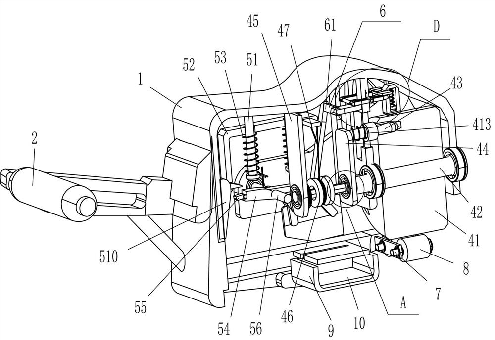
[0023] refer to Figure 1-Figure 6 , an iron sheet fixed-distance slotter for building an iron shed, comprising a casing 1, a handle 2, a multi-slot plate 3, a driving mechanism 4 and a cutting mechanism 5, the outer left side of the casing 1 is fixedly connected with the handle 2, the casing A multi-slot plate 3 is fixedly connected between the right side of the inner top of the body 1 and the right side of the inner front and rear sides, and a driving mechanism 4 is provided between the multi-slot plate 3 and the left side of the inner top of the housing 1, and the left side of the inner top of the housing 1 A cutting mechanism 5 is arranged between them, and the cutting mechanism 5 is fixedly connected with the driving mechanism 4 .

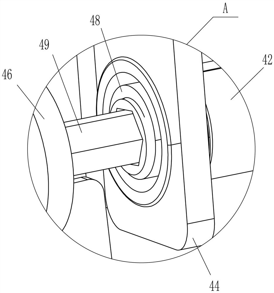
[0024] Drive mechanism 4 comprises cylinder 41, hollow rotating shaft 42, slide bar 43, fixed plate 44, riser 45, reel 46, backguy 47, hollow tube 48, hexagonal rod 49, contact rod 411, scroll spring 412 and Back-moving spring 413, a riser 45...

Embodiment 2

[0030] refer to figure 2 , image 3 and Figure 7 Compared with Embodiment 1, the main difference of this embodiment is that in this embodiment, a positioning mechanism 6 is also included, and the positioning mechanism 6 includes an n-shaped plate 61, a u-shaped bar 62, a return block 63, a swing frame 64, a second Two torsion springs 65 and the third spring 66, a u-shaped bar 62 is affixed in the middle of the top right side of the housing 1, and the sliding type in the middle part of the u-shaped bar 62 is provided with a return block 63, and the top of the return block 63 is connected to the u-shaped The third spring 66 is connected between the inner bottom of the rod 62, and a swing frame 64 is hinged in the middle of the upper part of the multi-slot plate 3. The right end of the swing frame 64 contacts and cooperates with the return block 63. The second torsion spring 65 is fixedly connected with an n-type plate 61 between the front and rear sides cutter 54 top right s...

Embodiment 3

[0033] refer to figure 1 and figure 2 , the main difference between this embodiment and embodiment 1 and embodiment 2 is that in this embodiment, there are also rollers 7 and guide cylinders 8, and the rotating type is evenly spaced between the lower right side of the front and rear sides of the housing 1. A roller shaft 7 is connected, and a guide cylinder 8 is fixedly connected to the roller shaft 7 .

[0034] It also includes a collection frame 9 and a permanent magnet 10 , a collection frame 9 that can collect iron filings is slid between the lower parts of the housing 1 , and the bottom of the collection frame 9 is fixed with a permanent magnet 10 .

[0035] When the housing 1 is placed on the edge of the iron sheet, the iron sheet is still in contact with the guide cylinder 8, and then the operator pulls the handle 2 to move the housing 1 on the iron sheet, and the guide cylinder 8 rolls on the iron sheet. In this way, the device can be moved more smoothly on the iron...


PUM


Abstract

The invention relates to a slit, in particular to an iron sheet fixed-distance slit for building an iron shed. The technical problem is how to design a kind of iron sheet fixed-distance slit device that can be more convenient for people to cut and slit the iron sheet and has high work efficiency for the construction of the iron sheet shed. An iron sheet fixed-distance slit for building an iron shed includes a casing, a handle is fixedly connected to the outer side of the casing, and the multi-slot plate is installed between the sides of the casing away from the handle; the driving mechanism is installed Between the inner side of the housing and the multi-slot plate, it is used to improve power. In the present invention, by putting the casing on the edge of the iron sheet, pulling the casing to move along the edge of the iron sheet to drive the roller to rotate, the cutter can swing intermittently to cut and slit the iron sheet, and the distance of cutting and slit is consistent, without the need for people to first The cutting position is measured well, and then cut after marking, the operation is more convenient and the work efficiency is also high.

Description

technical field [0001] The invention relates to a slit, in particular to an iron sheet fixed-distance slit for building an iron shed. Background technique [0002] Iron sheet: 1. The outer layer of iron. 2. Thin iron sheet. Generally refers to lead iron or tinplate. Such as: tin cans. 3. Iron-based metal oxides adhere to the surface of the steel. Features: The surface of the steel has black-gray or brown-red iron sheets in the form of scales, strips or blocks. In daily life, some people will build huts, and the top of the huts is built with iron sheets. There will be cuts and slits on the iron sheets so that the iron sheets can be assembled together to form the roof. [0003] At present, people first measure the position where the iron sheet needs to be cut with a measuring ruler, and then mark it. After marking, people use a cutting tool to cut and slit the iron sheet. There are many positions, and the cutting tool needs to be moved back and forth repeatedly. After a ...

Claims


Application Information

Patent Timeline
Patent Type & Authority Patents(China)
IPC IPC(8): B23D79/00B23Q5/027B23Q7/05B23Q11/00
CPCB23D79/00B23Q5/027B23Q7/05B23Q11/0064B23Q11/0067
Inventor 赵月养
Owner 吴艳美
Why Eureka
Try Eureka