Laser marking system

A laser marking and laser technology, which is applied in the field of laser marking, can solve the problem of workpieces becoming defective products, and achieve the effects of reducing defective rate, improving product yield and improving accuracy

Inactive Publication Date: 2020-06-23
林心
View PDF8 Cites 3 Cited by
  • Summary
  • Abstract
  • Description
  • Claims
  • Application Information

AI Technical Summary

Problems solved by technology

[0004] In view of the defects existing in the prior art, the technical problem to be solved by the present invention is to provide a laser marking system, which aims to solve the problem of deviation in the position of the printed image caused by the deviation in the placement position of the workpiece during the laser marking process. , so that the processed workpiece becomes a problem of defective products, improving product yield

Method used


Image

  • Laser marking system
  • Laser marking system
  • Laser marking system

Examples


Embodiment Construction

[0030] Below in conjunction with accompanying drawing and embodiment the present invention will be further described:

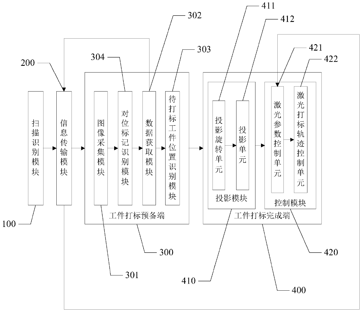
[0031] Such as Figure 1-3 As shown, in the first embodiment of the present invention, a laser marking system is provided, the system includes:

[0032] Infrared scanning equipment, laser equipment, scanning identification module 100, information transmission module 200, workpiece marking preparation terminal 300 and workpiece marking completion terminal 400; The workpiece 600 is scanned and identified; the scanning identification module 100 transmits the information of scanning and identifying the workpiece 600 to be marked to the workpiece marking preparation terminal 300 through the information transmission module 200; the laser device is used to emit laser light And irradiate the workpiece 600 to be marked to complete the marking; the workpiece marking preparation end 300 includes an image acquisition module 301, a data acquisition module 302 and a posit...


PUM


Abstract

The invention discloses a laser marking system. The system comprises infrared scanning equipment, laser equipment, a scanning identification module, an information transmission module, a workpiece marking preparation end and a workpiece marking completion end; the workpiece marking preparation end comprises an image acquisition module, a data acquisition module and a to-be-marked workpiece position identification module, wherein the image acquisition module is used for acquiring the contour and the alignment mark of a to-be-marked workpiece and forming a first image; the data acquisition module is used for acquiring a real-time actual coordinate and a workpiece intrinsic coordinate value; and the to-be-marked workpiece position identification module is used for solving a center coordinateand a rotation angle according to the real-time actual coordinate; the workpiece marking completion end comprises a projection module and a control module, the projection module projects a rotated marking pattern to a real-time projection coordinate, and the control module is used for controlling the laser equipment to carry out laser marking on the to-be-marked workpiece. According to the laser marking system, the marking pattern to be projected is rotated by solving the rotation angle, so that deviation between the position of the marked pattern and the preset position is effectively avoided, and the product yield is improved.

Description

technical field [0001] The invention relates to the technical field of laser marking, in particular to a laser marking system. Background technique [0002] Laser marking technology is one of the largest application fields of laser processing; laser marking is a chemical reaction in which a high-energy-density laser is used to locally irradiate the workpiece to vaporize the surface material or undergo a color change, thereby leaving a permanent mark. A marking method; laser marking can print a variety of text, symbols and images. [0003] In the prior art, when laser marking a workpiece, operators or mechanical transmission equipment are required to send the workpiece to be marked into the processing area, often due to deviations in the placement position, resulting in various characters and symbols printed out And images cannot be located in the ideal position on the workpiece to be marked, making the processed workpiece a defective product. Contents of the invention ...

Claims


Application Information

Patent Timeline
Patent Type & Authority Applications(China)
IPC IPC(8): B23K26/362B23K26/70B23K26/03
CPCB23K26/032B23K26/362B23K26/702B23K2101/007
Inventor 林心
Owner 林心
Why Eureka
Try Eureka