Wind energy machine

A technology for wind turbines and blades, which is applied to wind turbines, motors, and wind turbines at right angles to the wind direction, etc., can solve problems such as reducing the effect of wind turbine mechanisms, and achieve the effects of improving power generation efficiency and reducing resistance.

Inactive Publication Date: 2020-06-23
邓虎成
View PDF4 Cites 2 Cited by
  • Summary
  • Abstract
  • Description
  • Claims
  • Application Information

AI Technical Summary

Problems solved by technology

[0005] The structure design of the wind rotor of the existing vertical axis wind turbine is too complicated or too simple, and the wind force that receives the reverse resistance while being assisted is also very large, which greatly reduces the effect of the wind rotor mechanism

Method used


Image

  • Wind energy machine
  • Wind energy machine
  • Wind energy machine

Examples


Embodiment 1

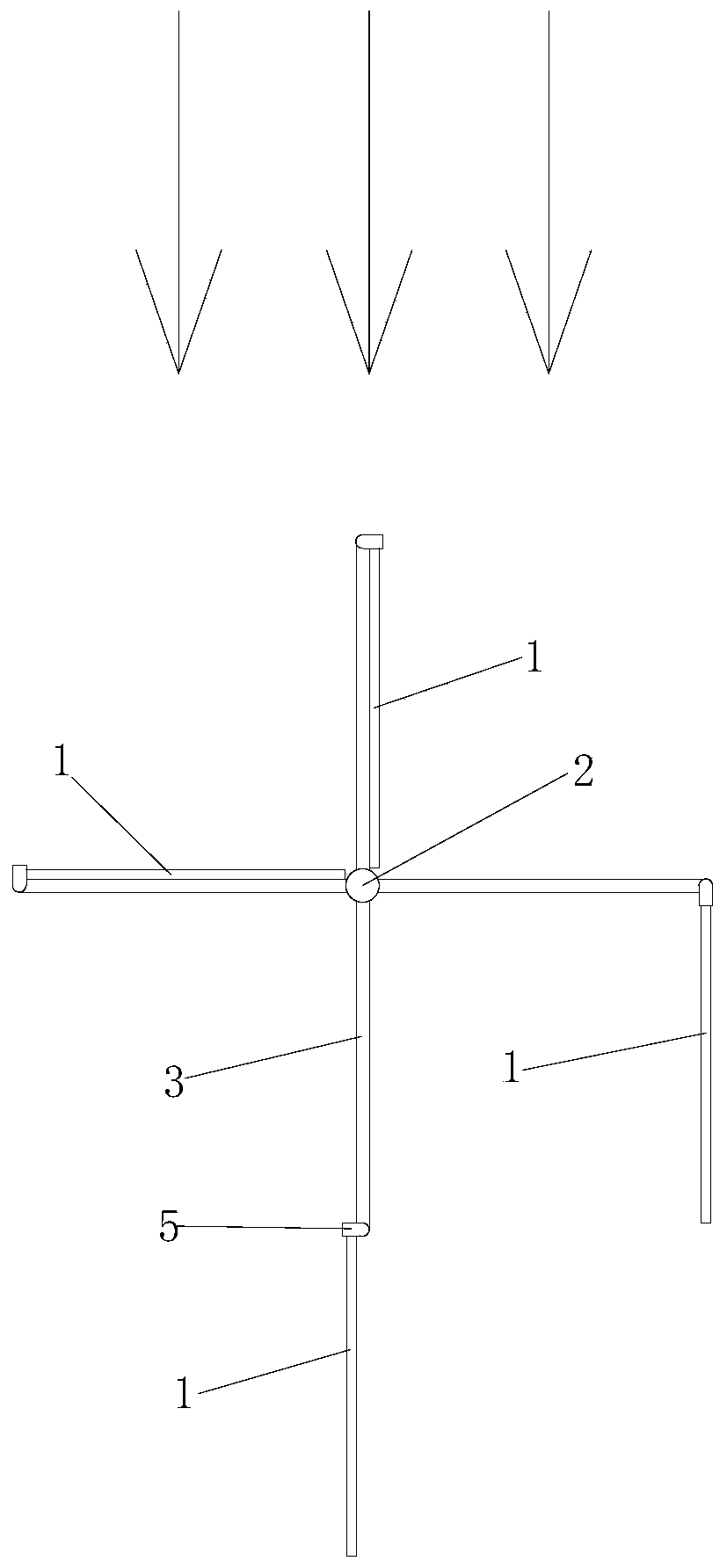
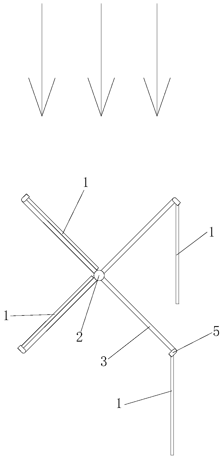
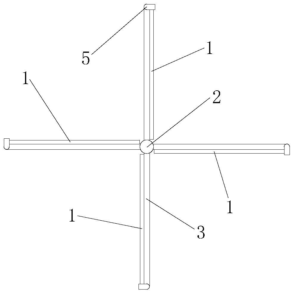
[0031] Such as Figure 1-4 as shown, figure 1 and figure 2 The arrow in the figure is the wind direction. This embodiment provides a wind energy machine, which includes a fan blade 1 and a central shaft 2. The upper end of the central shaft 2 is vertically connected with two support rod groups. The two support rod groups are perpendicular to each other and up and down. Staggered arrangement; each support rod group includes two support rods 3, and the two support rods 3 in each support rod group are symmetrically arranged with the central axis 2 as the central axis, which is equivalent to four support rods 3 at 90° The distance is evenly distributed around the central axis 2, and the stability of the central axis 2 can also be guaranteed when the support rod 3 drives the central axis 2 to rotate; the ends of the four support rods 3 away from the central axis 2 are all movably connected with a wind turbine. leaves 1, and the four fan blades 1 are all arranged on the same side...

Embodiment 2

[0034] This embodiment is a further improvement made on the basis of Embodiment 1. The specific differences between this embodiment and Embodiment 1 are:

[0035] What needs to be further explained in this embodiment is that the end of each support rod 3 away from the central axis 2 is vertically connected with a vertical rod 4. At this time, the vertical rod 4 is parallel to the central axis 2, and each fan blade 1 is flexibly connected to the On the corresponding vertical rod 4, the fan blade 1 is movably connected to the vertical rod 4, so that the connection points of the fan blade 1 can be increased, so that the connection between the fan blade 1 and the vertical rod 4 is easier than the connection between the fan blade 1 and the support rod 3. Stable, to ensure the stable rotation of the fan blade 1 and the subsequent continuous work.

Embodiment 3

[0037] This embodiment is a further improvement made on the basis of Embodiment 2. The specific differences between this embodiment and Embodiment 2 are:

[0038] What needs to be further explained in this embodiment is that each support rod 3 is vertically connected to the middle part of the corresponding vertical rod 4, so that the stability of the vertical rod 4 can be maintained, thereby ensuring the stress stability of the fan blade 1. During the rotation of the blade, it is natural to ensure the stability of the support rod 3 when it is subjected to the reverse force of the blade 1 to a greater extent, thereby ensuring the stable rotation of the central axis, making the generated mechanical energy more stable, and the conversion of mechanical energy into electrical energy is naturally easier. more efficient.


PUM


Abstract

The invention belongs to the technical field of wind driven generators, and discloses a wind energy machine. The wind energy machine comprises fan blades and a center shaft, wherein the upper end of the center shaft is perpendicularly connected with two supporting rod sets, and the two supporting rod sets are perpendicular to each other and arranged in an up-and-down staggered mode; each supporting rod set comprises two supporting rods, and the two supporting rods in each supporting rod set are symmetrically arranged with the center axis as a center axis; the ends, away from the center shaft,of the four supporting rods are each movably connected with a fan blade, and the four fan blades are arranged on the same side of the corresponding supporting rods. According to the wind energy machine, the fan blades following the wind direction are blown by wind power to the maximum extent, and the rotation of the fan blades is accelerated, so that the rotation of the center shaft is accelerated, and the power generation efficiency is improved; and the fan blades against the wind direction are rapidly opened to the position parallel to the against wind, and the influence of natural wind is reduced to the maximum extent, so that the resistance is rapidly reduced, and through cooperation with the fan blades following the wind direction, the power generation efficiency is integrally improved.

Description

technical field [0001] The invention belongs to the technical field of generators, and in particular relates to a wind energy machine. Background technique [0002] A wind energy machine is a centralized device that transforms and utilizes wind energy. It can directly use the mechanical energy it generates, or convert its mechanical energy into electrical energy for use in wind power generators. [0003] A wind turbine is a power device that converts wind energy into mechanical work, which drives the rotor to rotate, and finally outputs alternating current. Wind turbines are generally composed of components such as wind rotors, generators (including devices), steering devices (tail fins), towers, speed-limiting safety mechanisms, and energy storage devices. The working principle of a wind turbine is relatively simple. The wind rotor rotates under the action of the wind, which converts the kinetic energy of the wind into the mechanical energy of the wind rotor shaft, and the...

Claims


Application Information

Patent Timeline
Patent Type & Authority Applications(China)
IPC IPC(8): F03D3/06
CPCF03D3/005F03D3/061F03D3/062Y02E10/74
Inventor 邓虎成
Owner 邓虎成
Why Eureka
Try Eureka