
Wheel hub for direct driving type wind turbine generator and direct driving type wind turbine generator

A wind turbine, direct-drive technology, applied in the assembly of wind turbines, wind turbines, wind energy power generation, etc., can solve the problems of large amount of steel, poor process practicability, and uncompact structure, and can simplify the number of parts and improve the The effect of product reliability and economy

Pending Publication Date: 2020-06-23
JIANGSU GOLDWIND SCI & TECH CO LTD
View PDF7 Cites 0 Cited by
  • Summary
  • Abstract
  • Description
  • Claims
  • Application Information

AI Technical Summary

Problems solved by technology

[0003] However, the wind turbine with this structure has the following disadvantages: (1) The generator and the hub are designed separately, the rotor is connected to the hub through the main shaft, the main shaft is long, the kinetic energy transmission chain is too long, and the transmission efficiency is low; 2) The distance between the hub and the base of the nacelle as a support point is relatively long, and the stability is poor; (3) Multiple parts need to be connected multiple times to realize the connection between the rotor and the hub, the structure is complicated, the maintenance-free is insufficient, and the reliability is low. (4) The assembly process of hub and power generation, generator and main frame is complicated, the installation process is cumbersome, and the process is poor in implementability; (5) The supporting structure of split hub and generator rotor is large in shape, not compact in structure, and the amount of steel used Many, high cost; separate assembly and transportation costs of generator and hub superimposed, economical is poor

Method used


Image

  • Wheel hub for direct driving type wind turbine generator and direct driving type wind turbine generator
  • Wheel hub for direct driving type wind turbine generator and direct driving type wind turbine generator
  • Wheel hub for direct driving type wind turbine generator and direct driving type wind turbine generator

Examples


Embodiment Construction

[0024] The embodiment of the present invention proposes a technical proposal of integrating the wheel hub and the generator housing. By forming the generator accommodating cavity on the hub, the hub is used to form the outer casing of the generator, and the rotor of the generator is installed on the outer casing of the generator formed by the hub. By building the generator into the hub, the number of connections and the volume, weight and cost of the generator set are greatly reduced. Hereinafter, embodiments according to the present invention will be described in detail with reference to the accompanying drawings.

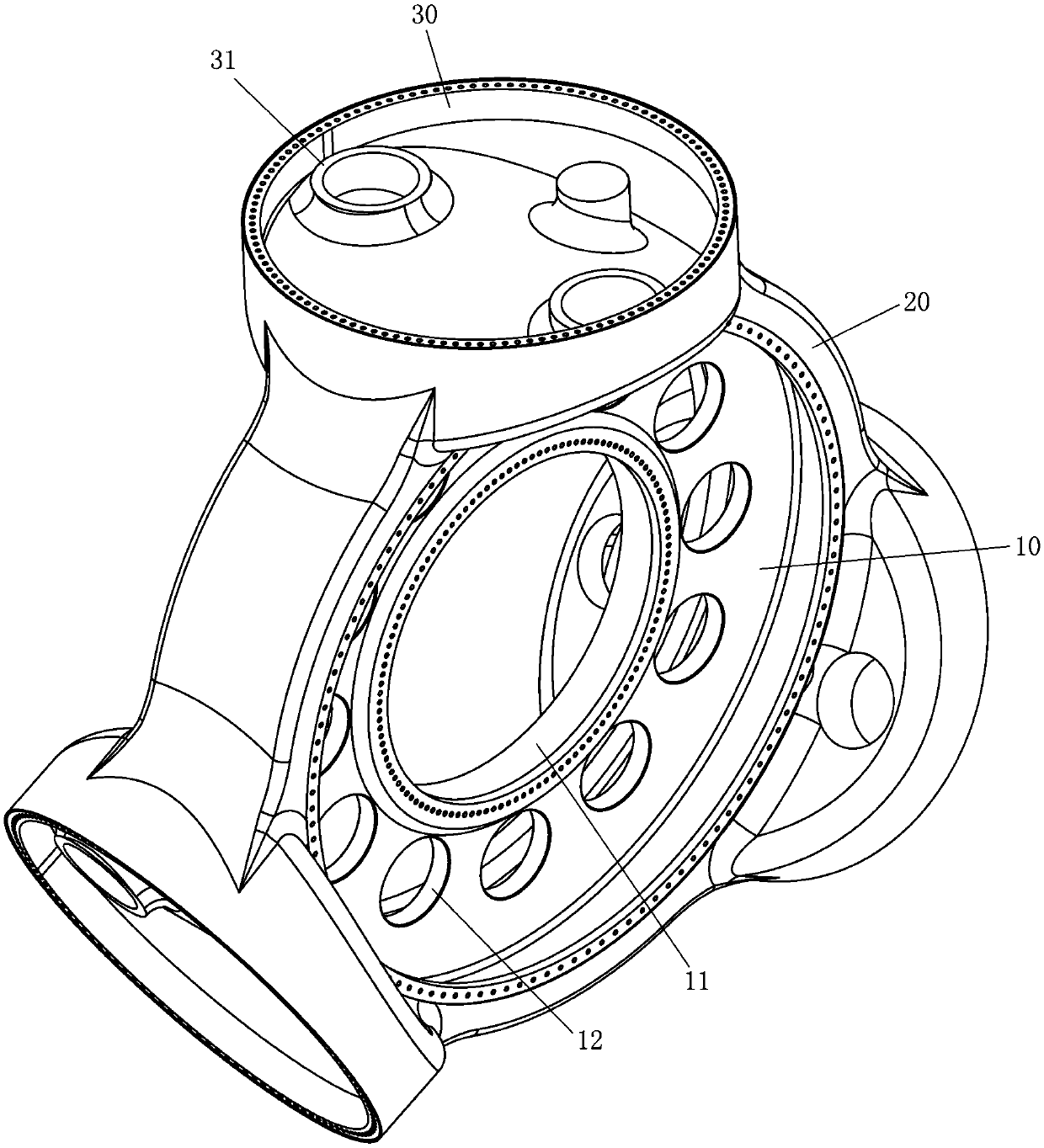
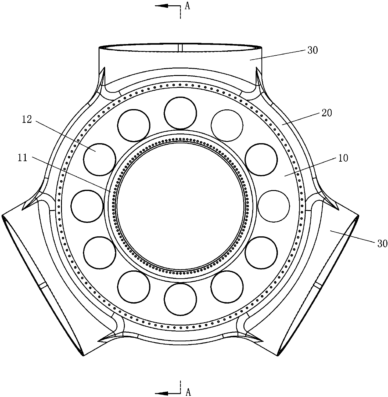
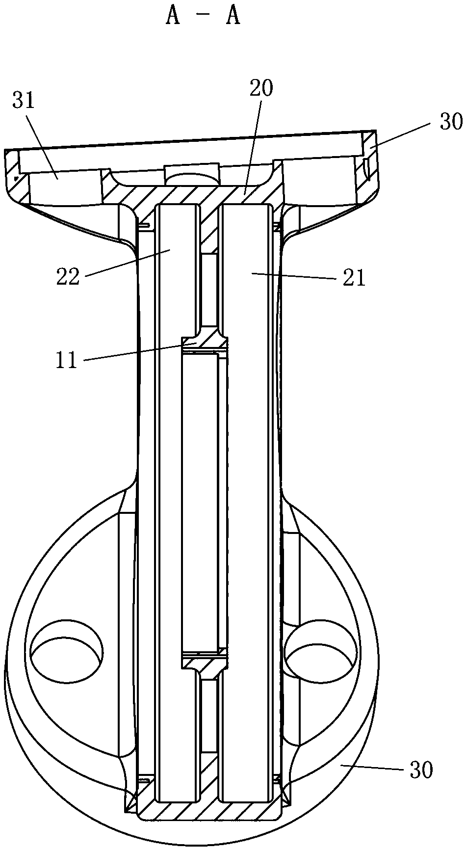
[0025] Such as Figure 1-3 As shown, the wheel hub 100 according to the embodiment of the present invention is generally disc-shaped, including a disc-shaped spoke part 10, and an outer flange 20 is formed on the outer circumference of the spoke part 10, and the outer flange 20 is formed along the axial direction of the wheel hub 100. Extend a predetermined leng...


PUM


Abstract

The invention provides a wheel hub for a direct driving type wind turbine generator and the direct driving type wind turbine generator. The wheel hub comprises a disc shaped wheel spoke part, an outerflange and at least two blade mounting flanges, wherein the outer flange extends by preset length in the axial direction from the outer circumference of the wheel spoke part to form a generator rotormounting shell; and the at least two blade mounting flanges are formed on the outer circumference of the wheel spoke part and are used for mounting the blades of the wind turbine generator. Accordingto the scheme, the generator is arranged in the wheel hub, so that the number of components, connected with the wheel hub, of the generator is reduced, a transmission chain is shortened, the transmission efficiency is improved and the product reliability and economy are improved.

Description

technical field [0001] The present invention relates to the technical field of wind power generators, more specifically, to a hub for a direct-drive wind generator and a direct-drive wind generator using the hub. Background technique [0002] With the rapid development of the wind power industry, horizontal axis direct drive wind turbines have been widely used in the wind power field. The conventional structure of this type of wind turbine is that the hub on which the blades are installed is designed separately from the direct-drive generator set, and the hub is mostly a star or spherical structure. The hub and the generator are two independent split structures. The hub is connected to the generator rotor through the main shaft to realize the transfer of mechanical energy from the impeller to the generator rotor, thereby generating electricity. [0003] However, the wind turbine with this structure has the following disadvantages: (1) The generator and the hub are designed ...

Claims


Application Information

Patent Timeline
IPC IPC(8): F03D80/00F03D13/10
CPCF03D80/00F03D13/10Y02E10/72
Inventor 刘勇于晨光
Owner JIANGSU GOLDWIND SCI & TECH CO LTD
Learn More