Gas regulating valve core structure

A technology for gas adjustment and valve core, applied in the field of valve core, can solve the problems of rapid change of fire power, inaccurate control of fire power, poor control of the hole diameter of the side wall of the valve core, etc., and achieve the effect of precise fire power control

Inactive Publication Date: 2020-06-23
NINGBO FOTILE KITCHEN WARE CO LTD
View PDF21 Cites 0 Cited by
  • Summary
  • Abstract
  • Description
  • Claims
  • Application Information

AI Technical Summary

Problems solved by technology

[0005] When the user uses it, many of the existing gas valves have a firepower that changes too quickly, and it is not easy to adjust the firepower required by the user
The matching of the inner and outer rings of firepower is not good, and users cannot adjust the firepower they need
There is no memory feel during the firepower adjustment process, and the firepower that the user wants cannot be quickly adjusted at the first time, etc.
In addition, the throttling hole is directly punched on the valve core. Since there is sealing grease between the valve core and the valve body, if the hole diameter of the side wall of the valve core is small, it is easy to be blocked by the sealing grease during the rotation of the valve core. , the multi-section valve is easy to block; the aperture of the hole on the side wall of the valve core is not easy to control, resulting in inaccurate control of the firepower

Method used


Image

  • Gas regulating valve core structure
  • Gas regulating valve core structure
  • Gas regulating valve core structure

Examples


Embodiment Construction

[0030] The present invention will be further described in detail below in conjunction with the accompanying drawings and embodiments.

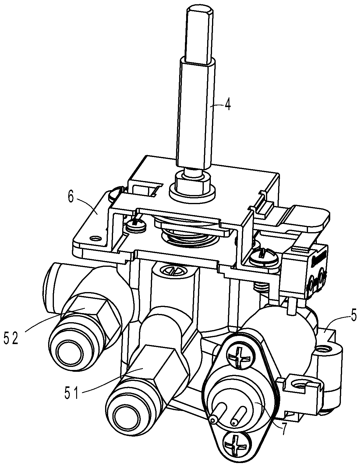
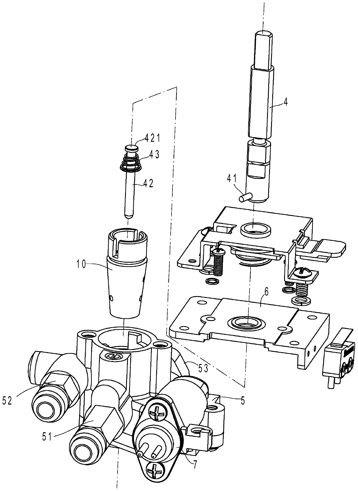
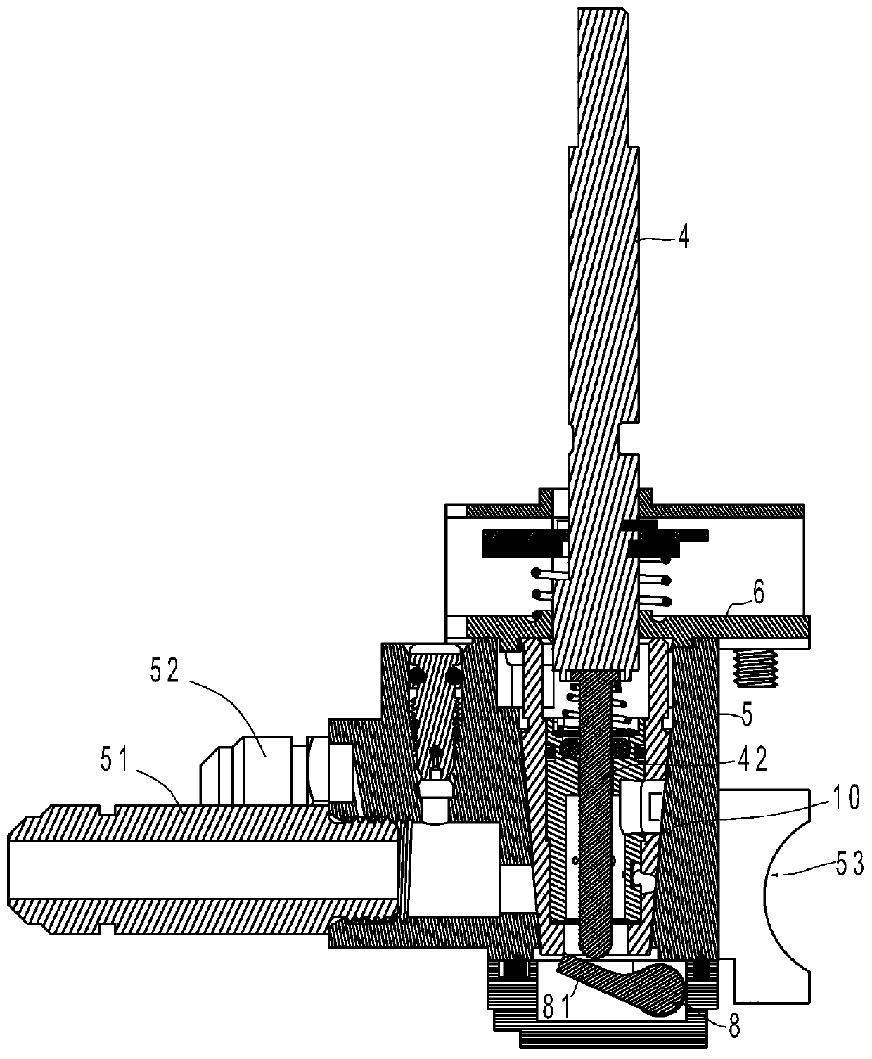
[0031] Such as figure 1 , figure 2 , image 3 with Figure 4 As shown, the gas regulating valve in this embodiment includes a valve body 5, a valve core 10, a solenoid valve 7, a push rod 8, a valve needle 42 and a valve stem 4. The valve body 5 has a valve chamber, and the valve body 5 has at least an inner An air inlet channel 53, an outer ring air outlet channel 51 and an inner ring air outlet channel 52 communicating with the valve cavity are provided, and the air inlet channel 53, the outer ring air outlet channel 51 and the inner ring air outlet channel 52 are respectively formed with outlet channels on the side wall of the valve cavity. Air holes, outer ring air intake holes and inner ring air intake holes.

[0032] The valve core 10 is rotatably arranged in the valve chamber of the valve body 5 and can adjust the flow rate of the ...


PUM


Abstract

The invention relates to a gas regulating valve core structure. The gas regulating valve core structure comprises a valve body, a valve core, a solenoid valve, a ejector rod, a valve needle and a valve stem, and is characterized in that the valve core comprises a core shell and a sleeve, the core shell is axially hollow, a circle of first outer ventilation holes matched with an inner ring gas outlet channel to adjust the air outlet flow are formed in the upper end of the side wall of the core shell, and a circle of second outer ventilation holes matched with an outer ring gas outlet channel toadjust the air outlet flow are formed in the lower end of the side wall of the core shell; and the sleeve is axially hollow and arranged in an inner cavity of the core shell in a sealed mode, a circle of first inner ventilation holes corresponding to the first outer ventilation holes are formed in the upper end of the side wall of the sleeve, a circle of second inner ventilation holes corresponding to the second outer ventilation holes are formed in the lower end of the side wall of the sleeve, and the valve needle is arranged in the sleeve in a penetrated mode. The valve core is assembled bythe core shell and the sleeve of a split body, first connection holes and second connection holes are not disturbed by sealing grease, and the accurate control of firepower is realized on the premiseof ensuring the smooth flow of fire holes.

Description

technical field [0001] The invention relates to a valve, in particular to a valve core applied to a gas cooker. Background technique [0002] Gas valves in various gas cookers are manually operated valves that control the supply of gas sources. Household gas cookers generally have an inner ring fire and an outer ring fire. A common dual-channel gas valve generally includes a valve body with an air inlet channel, an inner ring outlet channel and an outer ring outlet channel. The valve body is provided with a rotatable valve core. The lower part of the valve core is provided with a vent chamber, the valve body is pierced with a valve stem that can drive the valve core to rotate, and the valve stem can drive the valve core to rotate together. A series of adjusting fire holes of different sizes in the air outlet channel, and an arc-shaped inner ring fire hole for connecting the air intake channel and the inner ring air outlet channel. [0003] When in use, the ends of the inne...

Claims


Application Information

Patent Timeline
Patent Type & Authority Applications(China)
IPC IPC(8): F16K11/083
CPCF16K11/0836
Inventor 严力峰郑军妹钟健俞瑜
Owner NINGBO FOTILE KITCHEN WARE CO LTD
Why Eureka
Try Eureka