Grouting device for ecological restoration of concrete cracks

A technology of ecological restoration and grouting device, applied in building maintenance, construction, fermentation, etc., can solve the problems of unfriendly environment, high construction cost, secondary damage of concrete components, etc., and achieve the effect of enhancing the diffusion efficiency

Active Publication Date: 2022-01-11
SOUTHWEST PETROLEUM UNIV
View PDF18 Cites 2 Cited by
  • Summary
  • Abstract
  • Description
  • Claims
  • Application Information

AI Technical Summary

Problems solved by technology

In the prior art, in view of the problem of various width gaps in the interior of concrete components due to the accumulation of internal damage under long-term loads, repair methods such as surface sealing method, grooving filling method, and grouting plugging method are usually used. The repair method not only has high construction costs and is not friendly to the environment, but can also lead to secondary damage to concrete components. In view of the above defects, the applicant has developed a grouting device, which applies the technology of microbial induced calcium carbonate deposition (MICP) It is suitable for filling the cracks of concrete components, and at the same time, it can realize the targeted sealing of the leakage points deep in the cracks, enhance the diffusion efficiency of the grout, and then improve the sealing effect

Method used


Image

  • Grouting device for ecological restoration of concrete cracks
  • Grouting device for ecological restoration of concrete cracks
  • Grouting device for ecological restoration of concrete cracks

Examples


Embodiment 1

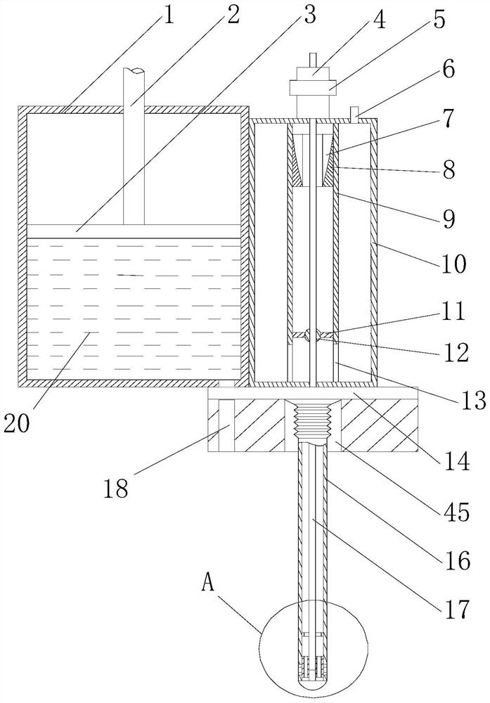
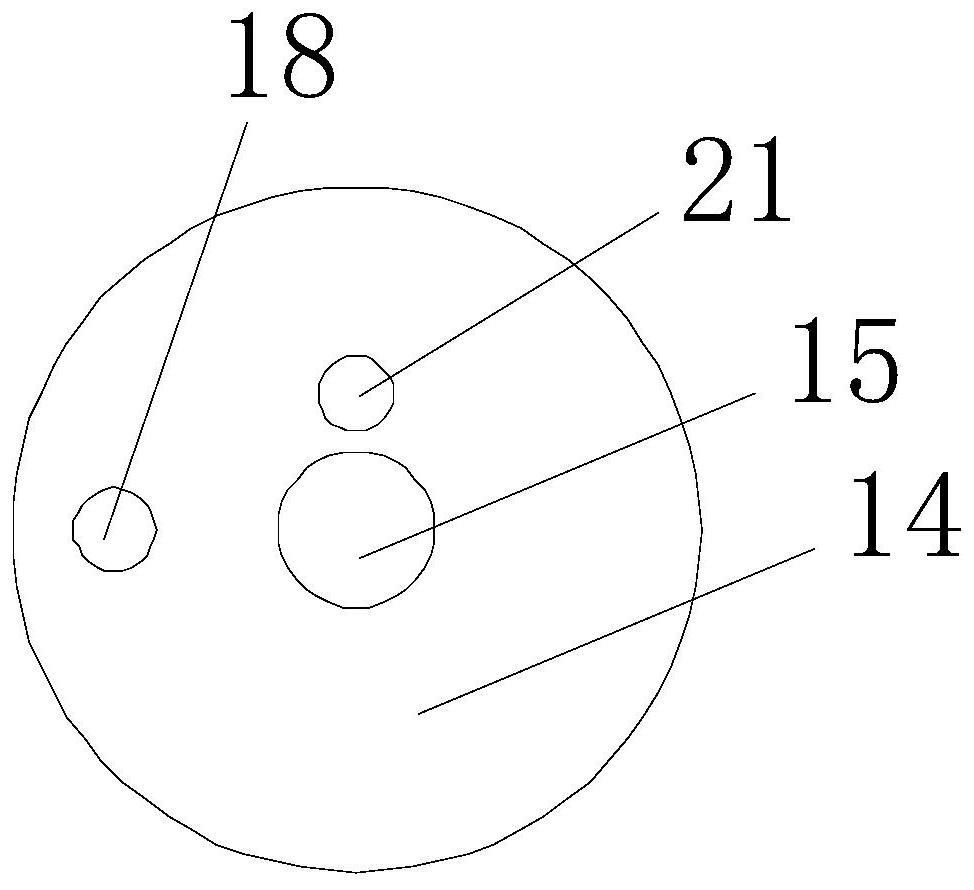
[0030] Such as Figures 1 to 5 As shown, this embodiment includes box body I1 and box body II10 arranged side by side. A piston 3 is arranged inside the box body I1, and a push rod 2 is arranged on the upper surface of the piston 3, and the upper end of the push rod 2 moves through the body of the box body II10. The top extends outwards, and an adjustment base 14 is provided at the bottom of the box body II10. The adjustment base 14 has grouting holes I15, grouting holes II18 and grouting holes III21. The bottom of the box body I1 is connected to the injection hole. The grouting hole II18 is connected, the bottom of the box body II10 is connected with the grouting hole I15, and the bottom of the adjustment base 14 is provided with a foldable guide tube 16 connected with the grouting hole I15, and the adjustment assembly is provided in the adjustment base 14. The adjustment assembly is used to control the opening and closing of the grouting hole I15 and the grouting hole II18; ...

Embodiment 2

[0036] Such as Figure 4 As shown, in this embodiment, on the basis of Embodiment 1, a columnar follower block 41 is provided on the outer peripheral wall of the end of the steel wire 17, and the outer peripheral wall of the follower block 41 is in contact with the inner wall of the guide tube 16. , and along the circumferential direction of the follower block 41, a plurality of communication holes 42 are opened on its end face, and a matching limit plate 40 is also provided on the inner circumferential wall of the guide tube 16, and the middle part of the limit plate 40 has a For the multiple rectangular through holes 39 , when the steel wire 17 drives the guide tube 16 to move, the outer peripheral wall of the follower block 41 keeps sealing the multiple grouting holes 43 .

[0037] When performing targeted injection on deep cracks, the guide catheter 16 is generally moved to the target point first, and then the grouting is started. By setting the follower block 41 at the en...

Embodiment 3

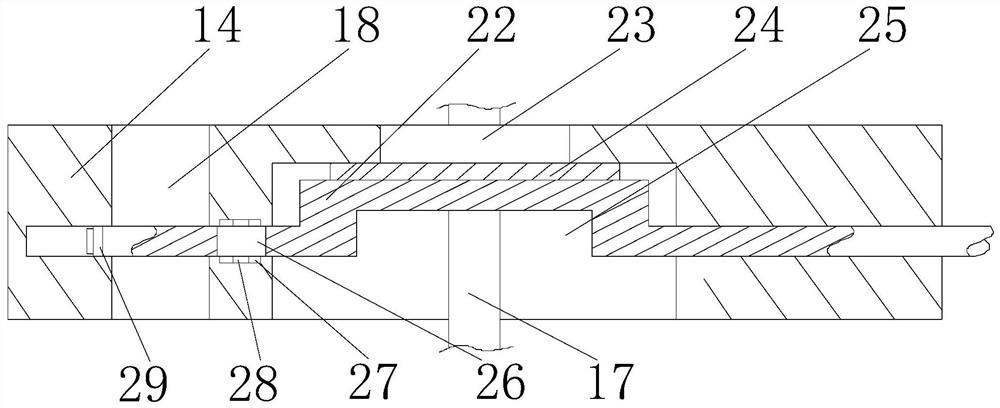
[0039] Such as Figures 1 to 3 As shown, this embodiment is based on Embodiment 1, the adjustment assembly includes a main shaft, a crank arm arranged in the middle of the main shaft, a plug plate 24 is provided on the crank arm, and the grouting holes I15 are interconnected by The liquid inlet 23 and the liquid outlet 25 are composed, the liquid inlet 23 communicates with the inside of the casing II 10, the liquid outlet 25 communicates with the beginning of the guide pipe 16, and the inner diameter of the liquid outlet 25 is smaller than the horizontal length of the plug plate 24, and The inner diameter of the liquid outlet 25 is larger than the inner diameter of the liquid inlet 23, the crank arm is placed in the liquid inlet 23, and one end of the main shaft moves through the adjustment base 14 and then extends outward. Blind hole, the grouting hole II18 communicates with the liquid inlet 23 through the guide hole, the other end of the main shaft moves through the guide ho...


PUM


Abstract

The invention discloses a grouting device for ecological restoration of concrete cracks. The grouting device comprises a box body I and a box body II which are arranged side by side. A grouting hole I, a grouting hole II and a grouting hole III are formed in an adjusting base. The bottom of the box body I communicates with the grouting hole II. The bottom of the box body II communicates with the grouting hole I. A guide pipe is arranged at the bottom of the adjusting base. An adjusting assembly used for controlling the grouting hole I and the grouting hole II to be opened and closed is arranged in the adjusting base. A steel wire vertically and movably penetrates through the box body II and the adjusting base and then extends towards the tail end of the guide pipe. A semicircular end is arranged at the end of the guide pipe. A plurality of grout spraying holes are formed in the side wall of the guide pipe. According to the grouting device, the MICP technology is applied to filling of the concrete component cracks, meanwhile, leakage point positions in the deep positions of the cracks can be blocked in a targeted mode, the diffusion efficiency of grout is improved, and thus the blocking effect is improved.

Description

technical field [0001] The invention relates to the field of building construction, in particular to a grouting device for ecological restoration of concrete cracks. Background technique [0002] Concrete components are widely used in the field of civil engineering because of their high strength, easy access to materials, strong moldability, and good integrity. However, concrete is a typical porous and brittle material. Affected by unfavorable factors such as temperature changes and corrosion aging, under long-term loads, cracks of various widths will inevitably develop inside components due to damage accumulation, which will reduce the mechanical properties of components and threaten the durability of structures. sex. Traditional concrete structure crack repair methods such as surface sealing method, grooving filling method, and grouting plugging method have a series of problems such as high energy consumption, high cost, unfriendly environment, and even secondary damage t...

Claims


Application Information

Patent Timeline
Patent Type & Authority Applications(China)
IPC IPC(8): E04G23/02C12P3/00
CPCE04G23/0211C12P3/00
Inventor 郭亮文海旭赵金龙路益王云翔彭颐祈王保权戴启辰李媛媛廖明伟郭豪何肖玉邢雷张敏何妮郭馨艺王雅坤王梓同鄢睿吴海龙王泓智刘丰威
Owner SOUTHWEST PETROLEUM UNIV
Why Eureka
Try Eureka