
Charging mechanism of robot charging station

A charging station and robot technology, applied in battery circuit devices, circuits, current collectors, etc., can solve problems such as potential safety hazards, poor contact stability between robots and charging stations, etc., to improve safety, compact structure, and prevent false triggering. Effect

Active Publication Date: 2020-06-23
SHENYANG SIASUN ROBOT & AUTOMATION
View PDF8 Cites 0 Cited by
  • Summary
  • Abstract
  • Description
  • Claims
  • Application Information

AI Technical Summary

Problems solved by technology

The charging station should meet the requirements of charging when it is in contact with the robot, and stop the power supply when the robot leaves. However, there are still deficiencies in the protective limit device and false trigger protection mechanism of the existing charging station, resulting in poor contact stability between the robot and the charging station. ,There are security risks

Method used


Image

  • Charging mechanism of robot charging station
  • Charging mechanism of robot charging station
  • Charging mechanism of robot charging station

Examples


Embodiment Construction

[0017] The present invention will be described in further detail below in conjunction with the accompanying drawings.

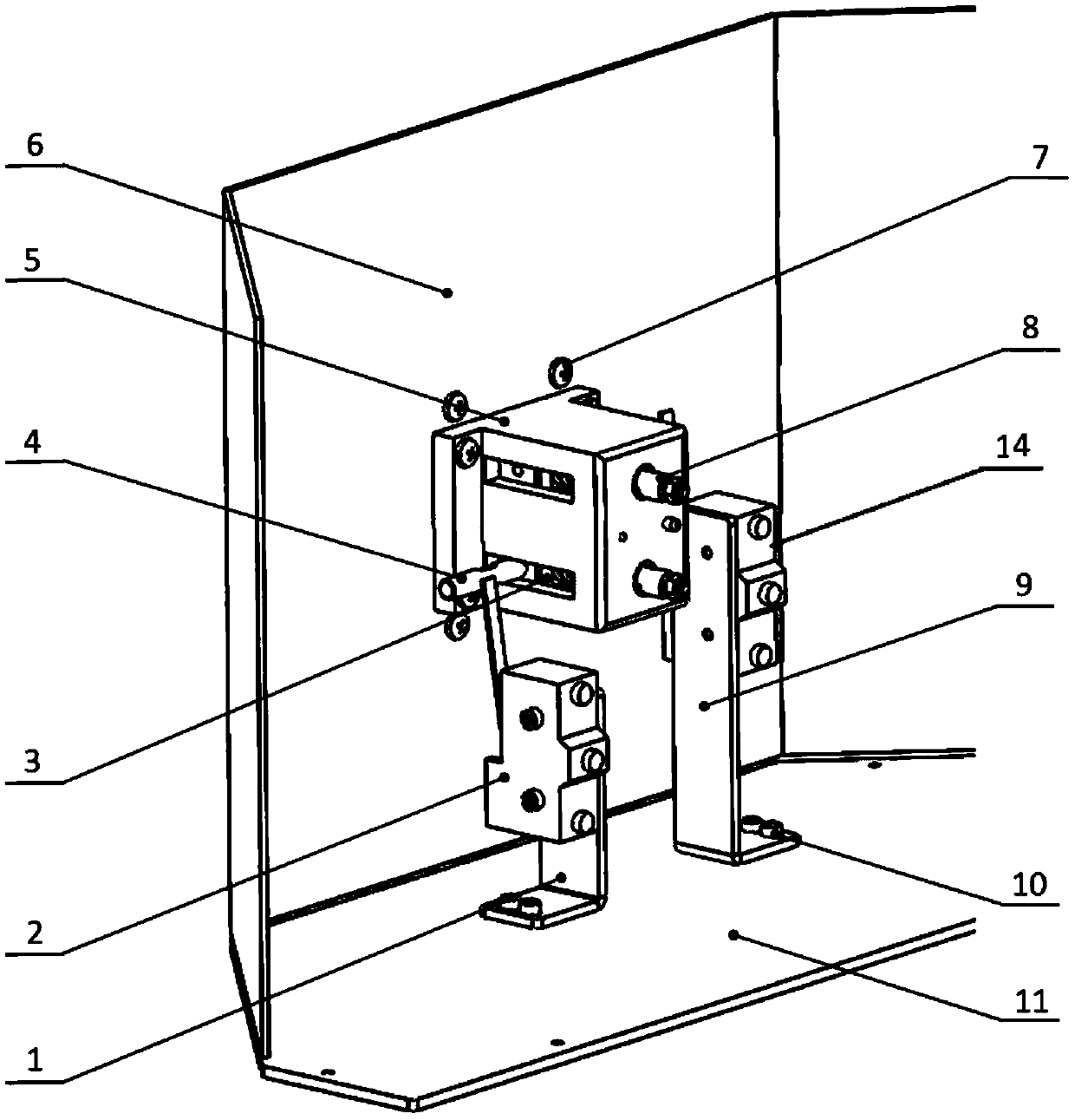
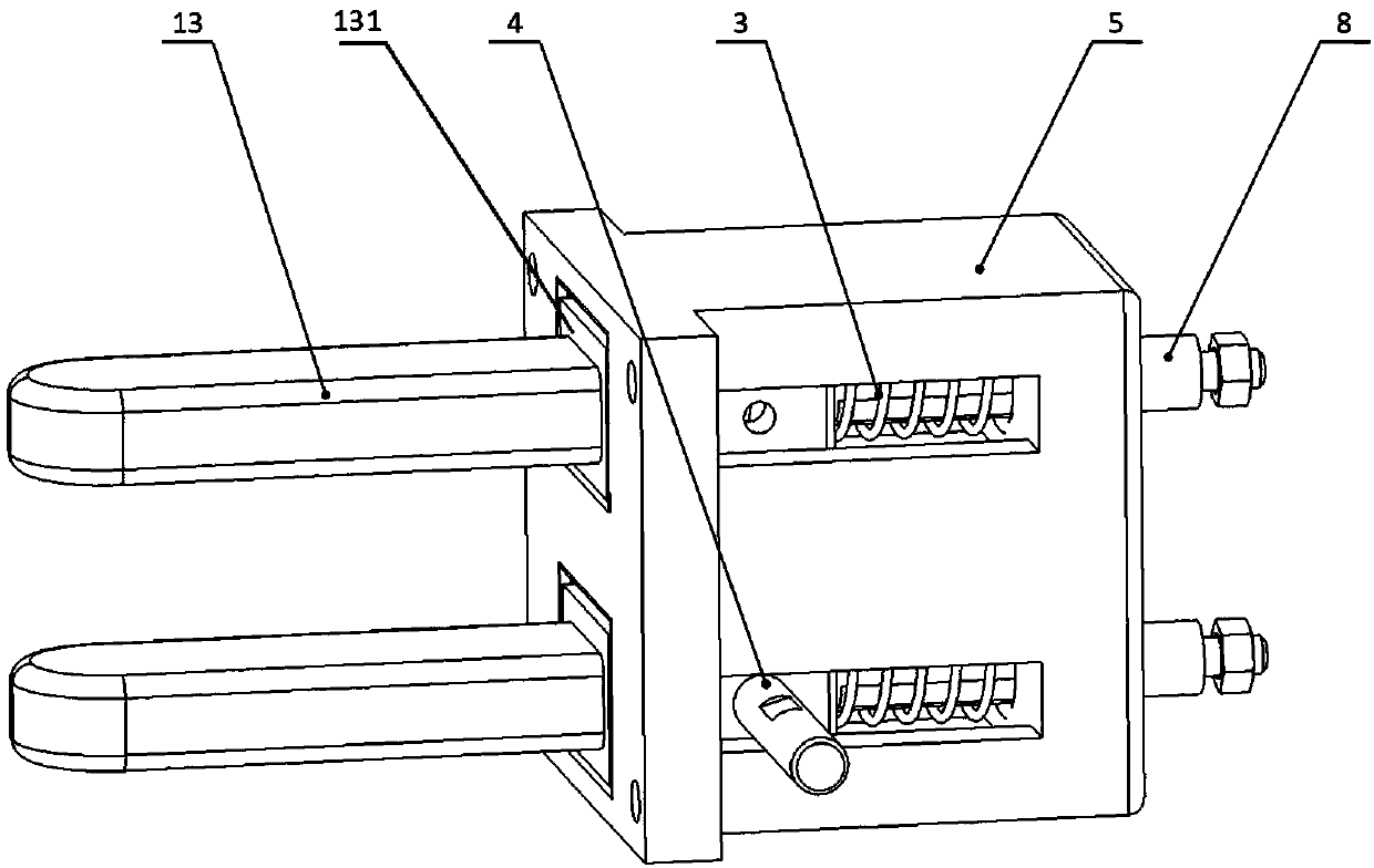
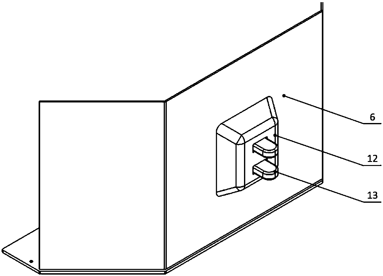
[0018] Such as Figure 1~3 As shown, the present invention includes a housing, an inner insulating seat 5, a first micro switch 2 and a second micro switch 14, and the inner insulating seat 5, the first micro switch 2 and the second micro switch 14 are all located at the In the housing, wherein the inner insulating seat 5 is installed on the front shell 6 of the housing, the first micro switch 2 and the second micro switch 14 are respectively arranged on both sides of the inner insulating seat 5, as figure 2 As shown, the inner insulating seat 5 is provided with a movable first strut and a second strut, and the front end of each strut is provided with a hole that extends out of the inner insulating seat 5 and passes through the housing. The copper bar 13 for connecting electricity, the rear end of each sliding column extends to the outside of the inner insu...


PUM


Abstract

The invention relates to the technical field of robot charging, and particularly relates to a charging mechanism of a robot charging station. The charging mechanism comprises a shell, an inner insulating seat, a first microswitch and a second microswitch, wherein the inner insulating seat is arranged in the shell; the first microswitch and the second microswitch are respectively arranged at two sides of the inner insulating seat; a first sliding column and a second sliding column are arranged in the inner insulating seat; the front end of each sliding column is provided with a power connectioncopper bar, and the rear end of each sliding column is provided with a power connection column; each sliding column is sleeved with a spring; the springs are arranged between the rear end of the power connection copper bar and the rear wall of the inner insulating base; trigger blocking columns are arranged on the outer sides of the first sliding column and the second sliding column; the triggerblocking column on the first sliding column is matched with the first microswitch; and the trigger blocking column on the second sliding column is matched with the second microswitch. Stable contact and continuous power supply of the electrodes are guaranteed, walking errors in the autonomous charging process of the robot can be made up, mechanical collision is prevented, the microswitch is additionally arranged for charging confirmation, false triggering is prevented, and the safety is improved.

Description

technical field [0001] The invention relates to the technical field of robot charging, in particular to a charging mechanism of a robot charging station. Background technique [0002] In recent years, with the vigorous development of the robot industry, the application of robot automatic charging technology has become more and more extensive, and the robot charging station is a key component to realize the robot autonomous charging technology, and its structural design is very important. The charging station should meet the requirements of charging when it is in contact with the robot, and stop the power supply when the robot leaves. However, there are still deficiencies in the protective limit device and false trigger protection mechanism of the existing charging station, resulting in poor contact stability between the robot and the charging station. ,There are security risks. Contents of the invention [0003] The purpose of the present invention is to provide a chargin...

Claims


Application Information

Patent Timeline
Patent Type & Authority Applications(China)
IPC IPC(8): H02J7/00H01R13/24H01R13/502H01R13/703
CPCH02J7/0042H01R13/2421H01R13/7035H01R13/502
Inventor 张克溪李健谭波悦王义峰王富刚刘鑫旭
Owner SHENYANG SIASUN ROBOT & AUTOMATION
Learn More