Motor rotor axial thrust device

A motor and rotor technology, which is applied in the field of high-speed and large-capacity motor improvement, can solve the problems of bearing bush vibration, grinding to the bearing bush base material, and increased energy consumption, so as to reduce the impact force and rebound force of the shaft channel, and reduce the axial displacement of the rotor. force, to ensure normal results

Pending Publication Date: 2020-06-23
上海正容工贸有限公司
View PDF0 Cites 1 Cited by
  • Summary
  • Abstract
  • Description
  • Claims
  • Application Information

AI Technical Summary

Problems solved by technology

[0005] However, in actual use, after the motor runs for a period of time, the electric rotor will move irregularly in the axial direction, some move to the left or right, and some rotors will move left and right It keeps moving back and forth, and the reasons for the above-mentioned movement phenomena are still unknown.
This kind of rotor axially shifts, causing the end face of the journal to push against the Babbitt alloy on the end face of the bearing pad during operation, and the Babbitt alloy on the end face of the bearing pad is gradually worn away, such as figure 2 As shown, in severe cases, even the babbitt alloy on the end face can be ground and then continue to grind to the base metal of the bearing bush
When the end face of the journal is pushed against the end face of the bearing bush, it will also cause the bearing bush to vibrate, generate heat, and increase energy consumption; the most dangerous thing about the large axial shift of the electric rotor is that the rotor rapidly shifts left and right, causing the journal The end face continuously rubs against the end face of the bearing bush, resulting in a rebound force that increases the shaft channeling force, and the dynamic and static two end faces are close to each other, and the lubricating oil cannot penetrate, resulting in dry friction of the metal on the two end faces, and the bearing bush and journal are instantly melted. Serious threats to the security and normal operation of user equipment

Method used


Image

  • Motor rotor axial thrust device
  • Motor rotor axial thrust device
  • Motor rotor axial thrust device

Examples


Embodiment Construction

[0027] The present invention will be further described in detail below in conjunction with examples, but the embodiments of the present invention are not limited thereto.

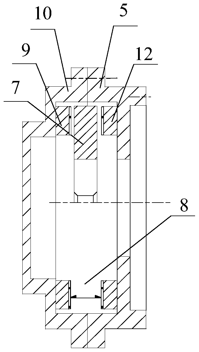
[0028] Such as Figure 3~5 As shown, the motor rotor axial thrust device provided by this embodiment has a chamber-shaped casing, and the casing is composed of two parts, the front seat 5 and the rear cover 10. The front seat 5 and the rear cover 10 have screw holes that match each other. It is integrally connected by bolts, and all other components of the thrust device are arranged in the shell.

[0029] In order to enable those skilled in the art to have a clearer understanding and understanding of this embodiment, the structure of each component and the assembly and adjustment process are introduced below:

[0030] (1) Front seat

[0031] Such as Figure 4 Shown, front seat 5 is joined to form by upper and lower two half garden pedestal bodies, and the pedestal body horizontal joint surface has bolt c...


PUM


Abstract

The invention discloses a pump motor rotor axial thrust device, which comprises a housing of the motor rotor axial thrust device composed of a front base (5) and a rear cover (10); thrust mechanism components which are arranged in the housing and comprise a rear cover pressure bearing ring (9) and a front base pressure bearing ring (12); and a thrust disc (7) which is arranged between the rear cover pressure bearing ring (9) and the front base pressure bearing ring (12). According to the invention, when the motor operates, the thrust disc enables the motor rotor to be at a designed working position in the axial direction; when the motor rotor is about to generate axial out-of-control large shifting, the two pressure bearing rings of the device can bear axial shifting force in different directions on the thrust disc, and the axial shifting amount of the motor rotor is limited to be within 0.8-1.0 mm.

Description

technical field [0001] The invention belongs to the field of improving high-speed and large-capacity electric motors, and in particular refers to an axial thrust device for electric motor rotors. Background technique [0002] Large-scale high-speed motors generally refer to motors with speed: n=2970r / min, power: N=2000kw or more, which are mostly used in power station feedwater pumps, fans, and high-pressure water injection pumps in oil fields. The bearings of such motors have large rotors. , heavy weight, thick shaft, and high speed, the bearing comprehensive technical index has exceeded the use limit of rolling bearings (such as marble discs), so sliding bearings must be used. [0003] Such as figure 1 As shown, the sliding bearing has a simple structure and is divided into upper and lower halves, such as tiles, so it is called "bearing bush". The main shaft of the motor rotor is placed in the bearing bush. The part where the main shaft is located in the bearing bush is ...

Claims


Application Information

Patent Timeline
Patent Type & Authority Applications(China)
IPC IPC(8): H02K5/167
CPCH02K5/1672
Inventor 成榕
Owner 上海正容工贸有限公司
Why Eureka
Try Eureka