Refrigerating apparatus

一种制冷装置、控制装置的技术,应用在家用制冷装置、制冷机、制冷组件等方向,能够解决制冷循环陷入过载状态、无法充分加热、无法释放等问题

Inactive Publication Date: 2010-08-04
SANYO ELECTRIC CO LTD
View PDF1 Cites 11 Cited by
  • Summary
  • Abstract
  • Description
  • Claims
  • Application Information

AI Technical Summary

Problems solved by technology

That is, even if the hot water storage tank is filled with hot water, the cooling operation continues as long as the object to be cooled is not sufficiently cooled, but in this case, since the water from the hot water storage tank flowing in the heat exchanger is The high-temperature hot water is sufficiently heated, so the heat taken by the refrigerant from the object to be cooled by the evaporator cannot be released in the heat exchanger, resulting in the problem that the refrigeration cycle falls into an overload state
[0009] On the other hand, even if the object to be cooled is sufficiently cooled, the cooling operation continues as long as the hot water storage tank is not filled with hot water. However, in this case, due to the , the refrigerant cannot absorb heat from the object being cooled and therefore cannot adequately heat the water flowing in the heat exchanger
Furthermore, in this evaporator, since the refrigerant cannot absorb heat and evaporate, there is a fear that the liquid refrigerant will return to the compressor to cause liquid back phenomenon.

Method used


Image

  • Refrigerating apparatus
  • Refrigerating apparatus
  • Refrigerating apparatus

Examples


Embodiment 1

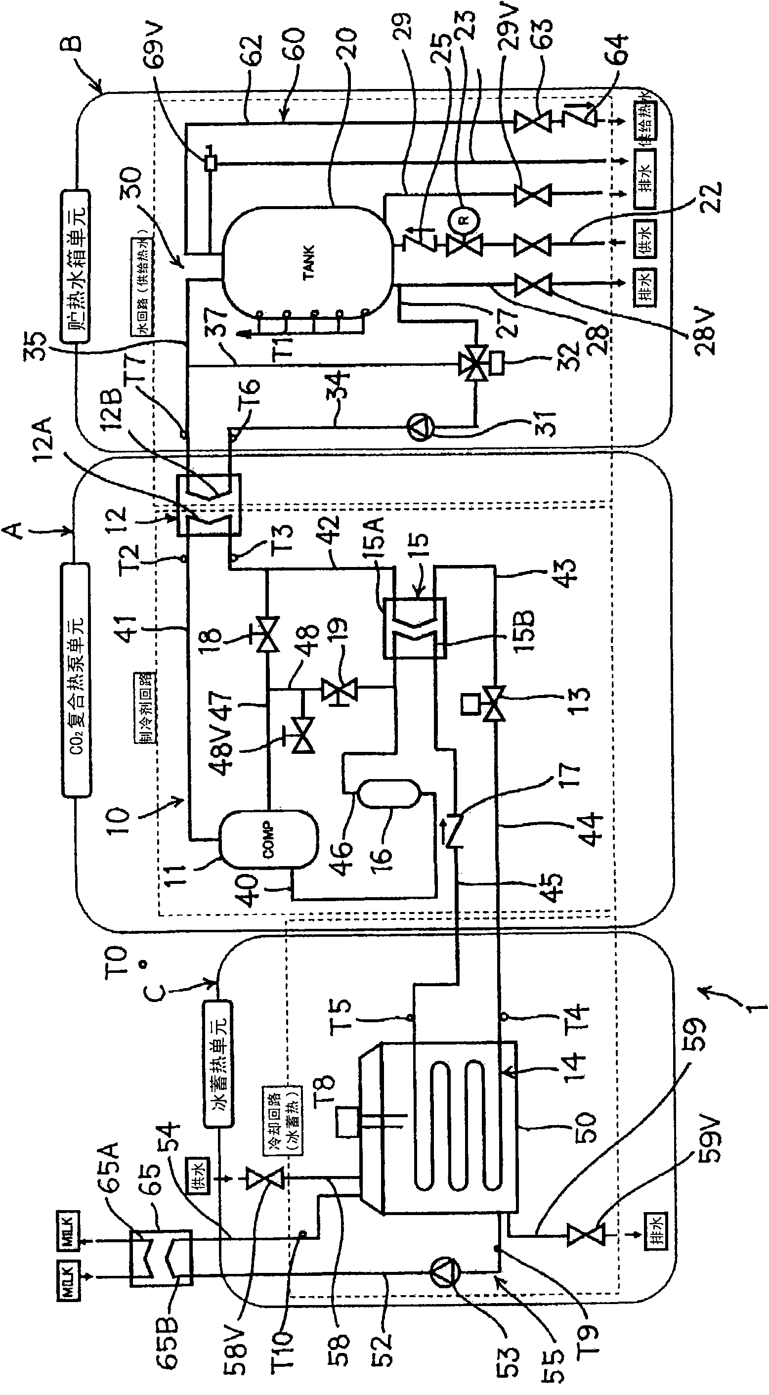
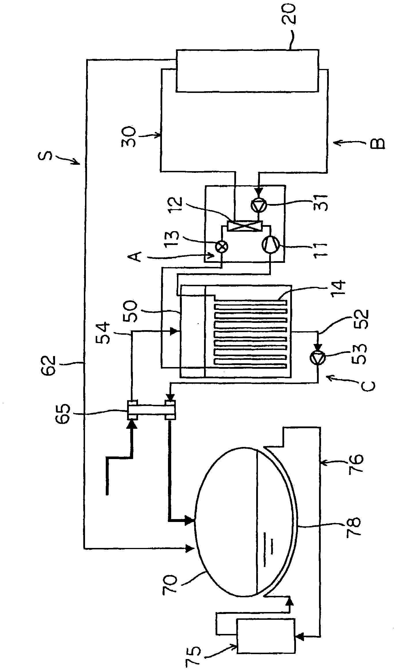
[0085] figure 1 A circuit diagram of a refrigeration device 1 to which an embodiment of the present invention is applied is shown. The refrigeration device 1 of the present embodiment includes: a heat pump unit (CO) having a refrigerant circuit 10 2 compound heat pump unit) A; hot water storage tank unit B having a hot water storage tank 20; a water circuit 30 for circulating water between the water heat exchanger 12 of the refrigerant circuit 10 and the hot water storage tank 20; The ice thermal storage unit (cold storage unit) C of the tank 50 .

[0086] The above-mentioned heat pump unit A is used to heat water from the hot water storage tank 20 (city water supplied to the hot water storage tank) to generate high-temperature water (hot water), and the ice heat storage tank of the ice heat storage unit C The water within 50 is cooled to produce ice. In the heat pump unit A of the embodiment, the refrigerant compressor 11, the refrigerant passage (radiator) 12A of the wate...


PUM


Abstract

The present invention provides a refrigerating apparatus which eliminates a disadvantage that a refrigerant circuit is overloaded and which can safely be operated. The refrigerating apparatus includes a control unit (Z) which starts the operation of a refrigerant compressor (11) of the refrigerant circuit (10) in response to an operation signal and which regulates an expansion valve (13) so that the temperature of a refrigerant in a water heat exchanger (12) becomes +80 DEG C or more and so that the temperature of the refrigerant in an evaporator (14) becomes 0 DEG C or less. The control unit (Z) detects a state of a case where a cold storage amount in an ice cold storage tank (50) of an ice cold storage unit (C) reaches a predetermined amount or more and a state of a case where the control unit (Z) judges that a hot water storage tank is full of hot water, after the elapse of a predetermined time from the start of the operation of the compressor, and stops the operation of the compressor (11) when one of the states is satisfied.

Description

technical field [0001] The present invention relates to a refrigeration device comprising a refrigerant circuit formed by connecting a refrigerant compressor, a water heat exchanger, a decompression device, and an evaporator through piping to form an annular refrigerant circuit, and the water heat exchanger is used to control the refrigerant flow through the water circuit. The circulating water from the hot water storage tank is heated, and the surrounding water is cooled by the evaporator to store cold. Background technique [0002] Conventionally, as a method of cooling an object to be cooled such as food or drink, a refrigeration device using an evaporation-compression refrigeration cycle has been widely used. In this type of refrigeration device, the object to be cooled is cooled by the heat absorption effect generated by the evaporation of the refrigerant in the evaporator, and the heat is released into the air by the heat dissipation of the refrigerant in the radiator....

Claims


Application Information

Patent Timeline
Patent Type & Authority Applications(China)
IPC IPC(8): F25B29/00F25B49/02
CPCF25B29/003F25B2600/2513F25D31/002F25B2309/061
Inventor 大竹雅久长谷川说川久保贤佐佐木英孝
Owner SANYO ELECTRIC CO LTD
Why Eureka
Try Eureka