Distal plug

A distal, cylindrical technology, applied in the field of auxiliary tools for bone cement femoral stem fixation, can solve the problem that the distal plug cannot be satisfied at the same time, and achieve the effect of improving the surgical effect

Pending Publication Date: 2020-06-26
山东大学齐鲁医院(青岛)
View PDF2 Cites 0 Cited by
  • Summary
  • Abstract
  • Description
  • Claims
  • Application Information

AI Technical Summary

Problems solved by technology

[0007] Therefore, the technical problem to be solved by the present invention is to overcome the technical defect that the distal plug in the prior art cannot meet the requirements of passing through the isthmus and being firmly fixed inside the medullary cavity, so as to provide a plug that can achieve the above-mentioned purpose. distal plug

Method used


Image

  • Distal plug
  • Distal plug
  • Distal plug

Examples


Embodiment 1

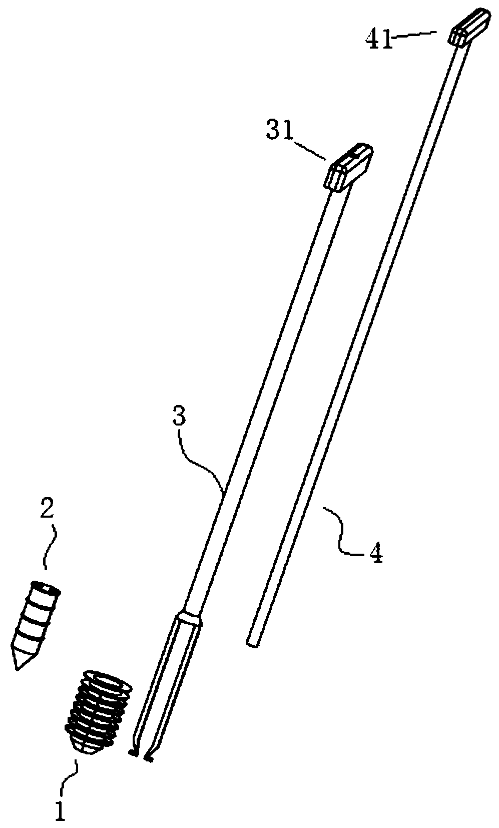
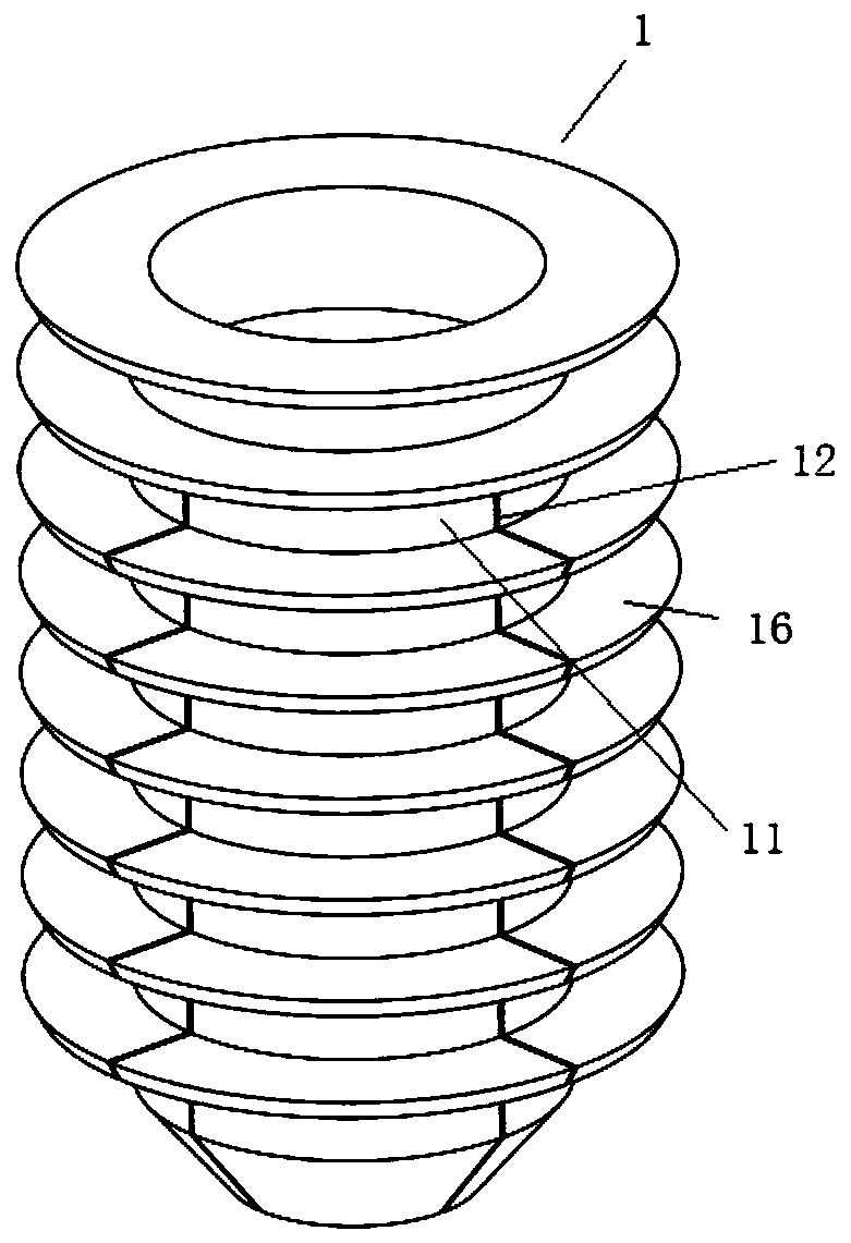
[0059] This embodiment provides a distal plug, such as figure 1 As shown, it includes: a plug sleeve 1, which is hollow, and can expand outward after being squeezed inside; a plug shaft 2, which can be inserted into the plug sleeve 1, and the plug shaft 2 has an initial position and a Squeeze position; at the initial position, the plug sleeve 1 does not expand outward; at the squeeze position, the plug sleeve 1 expands outward under the extrusion of the plug shaft 2; the operating handle 3 can be inserted into the The plug sleeve 1 behind the plug shaft 2 is detachably connected, and the plug sleeve 1 inserted into the plug shaft 2 can be sent to the target position; the driving member 4 is used to apply force to the plug shaft 2. After the external force drives the plug shaft 2 to move from the initial position to the extruding position, it is separated from the plug shaft 2 .

[0060] In the distal plug of this embodiment, after the plug shaft 2 and the plug sleeve 1 are as...

Embodiment 2

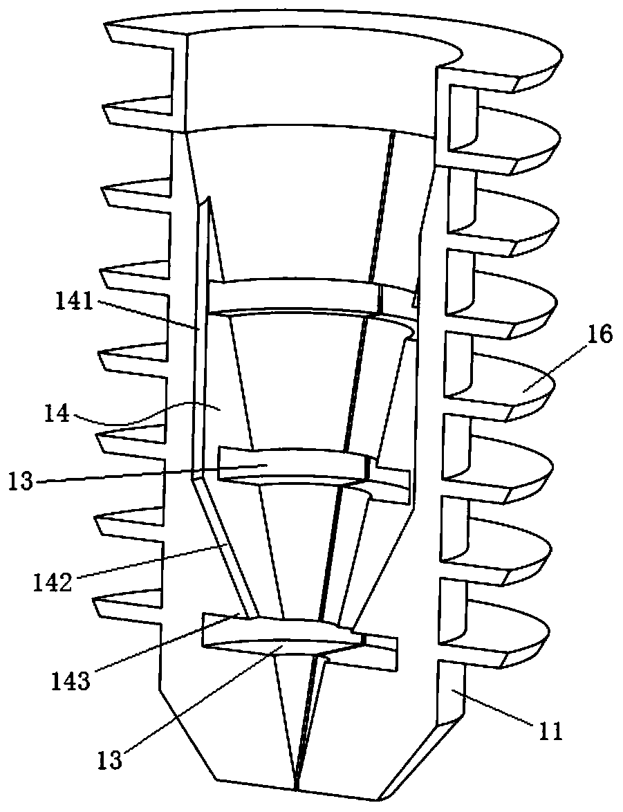
[0074] This embodiment provides a distal plug, which is a deformation based on Embodiment 1, the difference is that: Figure 7 , Figure 8 and refer to figure 2 , Figure 4 , Figure 5As shown, the inner wall of the cylindrical body 11 is provided with at least two first installation grooves 14 extending axially along the cylindrical body 11; the first installation grooves 14 communicate with the anti-off groove 13; The outer wall of the plug shaft 2 is provided with at least two second installation grooves 22 extending axially along the cylindrical body 11; when the first installation groove 14 is turned to face the opening of the second installation groove 22, a aisle;

[0075] The operating handle 3 has an operating end 31 and an inserting end 32, the inserting end 32 is provided with at least two elastic clips 33, the elastic clips 33 are provided with locking teeth 34, and the operating handle 3 passes through the When the passage is inserted into the plug sleeve 1,...


PUM


Abstract

The present invention provides a distal plug. The distal plug comprises a plug sleeve, a plug shaft, an operation handle and a driving part, wherein the plug sleeve is hollow and can expand outwards after being internally extruded; the plug shaft can be inserted into the plug sleeve, and the plug shaft has an initial position and an extrusion position inside the plug sleeve; in the initial position, the plug sleeve does not expand outwards; in the extrusion position, the plug sleeve expands outwards under the extrusion action of the plug shaft; the operation handle can be detachably connectedwith the plug sleeve inserted into the plug shaft, and can convey the plug sleeve inserted into the plug shaft to a target position; and the driving part is used for applying external force to the plug shaft to drive the plug shaft to move from the initial position to the extrusion position and then is separated from the plug shaft. The distal plug can pass through the isthmus and can be firmly fixed inside the medullary cavity to form a reliable barrier, so that bone cement is conveniently pressurized, sufficient micro-interlocking is formed between the bone cement and the cancellous bone ofthe femur, the femoral stem is firmly fixed, and the surgical effect can be improved.

Description

technical field [0001] The invention relates to the technical field of auxiliary tools for bone cement femoral stem fixation, in particular to a bone cement distal end plug for femoral stem fixation. Background technique [0002] With the aggravation of aging in modern society, there are more and more cases of femoral neck fracture in the elderly. In order to alleviate the suffering of patients and improve the quality of life of patients, hip replacement has become the preferred treatment method. Among elderly patients, a considerable proportion of patients need to use cemented femoral stems. The process of inserting the bone cement femoral stem is as follows: first place a distal plug in the femoral medullary cavity (about 2 cm from the distal end of the femoral stem), and then drive the dough-like bone cement into the femoral medullary cavity. , into the femoral stem to achieve firm fixation and ensure long-term use of the femoral stem. [0003] The function of the dist...

Claims


Application Information

Patent Timeline
IPC IPC(8): A61B17/88A61F2/46
CPCA61B17/8841A61F2/4601A61F2/4607
Inventor 孔杰张鹏杜建春万连平
Owner 山东大学齐鲁医院(青岛)
Why Eureka
Try Eureka