Plasma scalpel

A scalpel and plasma technology, applied in the field of ion scalpels, can solve problems such as difficult and precise surgical operations, large surgical trauma, and inconvenient surgical operations, and achieve long-term and stable suction effects, good effects, and surgical safety.

Pending Publication Date: 2020-02-07
CHENGDU MECHAN ELECTRONICS TECH
View PDF0 Cites 7 Cited by
  • Summary
  • Abstract
  • Description
  • Claims
  • Application Information

AI Technical Summary

Problems solved by technology

[0004] The technical problem to be solved and the technical task proposed by the present invention are to improve the prior art and provide a plasma scalpel, which solves the problem that the surgical trauma caused by the scalpel in the current technology is large, it is difficult to perform precise surgical operation, and the surgical operation is inconvenient. question

Method used


Image

  • Plasma scalpel
  • Plasma scalpel
  • Plasma scalpel

Examples


Embodiment 1

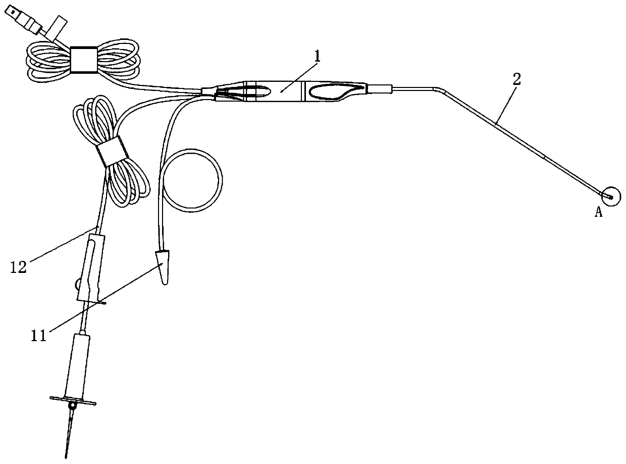
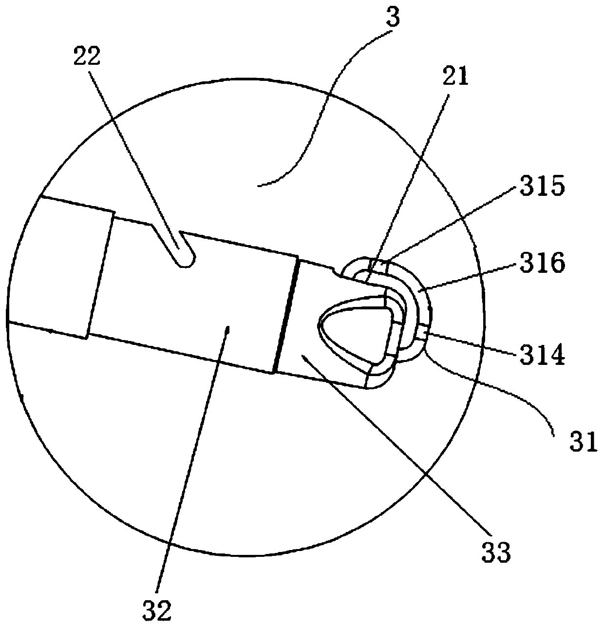
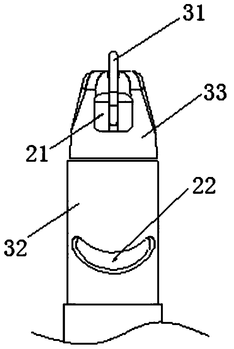
[0038] Such as Figure 1 to Figure 8 , A plasma scalpel, mainly comprising a handle 1, a shank body 2 and an electrode assembly 3. The proximal end of the shank body 2 is connected to the handle 1, and the diameter of the shank body 2 is preferably 2mm-4mm, An electrode assembly 3 is provided at the distal end of the arbor main body 2, and the electrode assembly 3 is electrically connected to a power supply assembly provided on the handle 1. The electrode assembly 3 includes a wire-shaped emitter 31, the diameter of the cross-section of the emitter 31 is (That is, the thickness) is 0.2-0.4mm, the emitter 31 bends and extends from the distal end surface of the arbor body 2 to the distal side of the arbor body 2, and the emitter 31 is curved in an arc shape as a whole (here the arc shape is mainly There are two situations: 1. The emitter 31 is curved and extends from the distal end surface of the arbor body 2 to the distal side of the arbor body 2, and the whole is in an arc shape...

Embodiment 2

[0046] Such as Picture 9 As shown, the difference from the first embodiment is that the liquid injection port 22 is provided on the insulating member 33, and specifically can be provided on the distal end surface of the insulating member 33, and the return pole 32 of the stainless steel tube is connected to the insulating member 33. The two independent through pipes form the liquid injection channel 24, and the two through pipes communicate with the liquid injection port 22.

Embodiment 3

[0048] Such as Picture 10 As shown, the difference from the first embodiment is that the opening direction of the suction port 21 is set on the distal end surface of the insulating member 33, the emitter 31 straddles the mouth of the suction port 21, and the emitter 31 can enter The tissue of the suction port 21 is ablated and broken, and the emitter 31 has a free end 312 deep into the suction port 21. The free end 312 penetrates into the insulation member 33 from the distal side of the insulation member 33 and penetrates into the suction port 21. Inside.


PUM


Abstract

The invention discloses a plasma scalpel. The plasma scalpel comprises a handle, a plasma scalpel rod body and an electrode assembly. A near end of the plasma scalpel rod body is connected to the handle, the far end of the plasma scalpel rod body is provided with the electrode assembly, the electrode assembly comprises a loop pole, a silk-thread-shaped emitting electrode and an insulating part connected to the far end of the plasma scalpel rod body and used for electrically insulating and separating the loop pole from the emitting electrode, and the emitting electrode integrally bends in an arc shape from the far end face of the insulating part and extends to the far end side face of the insulating part. The plasma scalpel disclosed by the invention can be used for accurately carrying outsurgical operation on diseased tissues, accidental injury to normal tissues can be effectively avoided, the emitting electrode can form plasma in multiple specific directions, different parts of the emitting electrode can be used for carrying out the surgical operation on target tissue, such as throats, which are not easy to expose, the surgical operation precision is high, the effect is good, surgical instruments do not need to be replaced during surgery, the surgical operation efficiency is high, the surgical time is shortened, and the surgical expenditure is saved.

Description

Technical field [0001] The invention relates to the technical field of surgical medical instruments, and in particular to a plasma scalpel. Background technique [0002] Low-temperature plasma ablation technology can realize tissue cutting, ablation and hemostasis at low temperature (40~70℃), and it is increasingly used in clinical surgery, especially in minimally invasive surgery of otolaryngology, head and neck surgery in. Usually the minimally invasive surgery has a small channel, and the operation area is narrow and complicated. The existing scalpel head has a large trauma to the tissue, and the accuracy of the operation is poor. It is easy to accidentally damage the normal tissue of the patient, and the normal structure after the operation is too large. Thus affecting its function, the unreasonable shape of the scalpel instrument brings great inconvenience to the operation of the doctor and affects the surgical field of vision. Summary of the invention [0003] As used here...

Claims


Application Information

Patent Timeline
Patent Type & Authority Applications(China)
IPC IPC(8): A61B18/12A61B18/14
CPCA61B18/1206A61B18/14A61B2018/00327A61B2018/00583A61B2018/00601A61B2018/126A61B2018/144
Inventor 肖旭平何朝东付波肖禹
Owner CHENGDU MECHAN ELECTRONICS TECH
Why Eureka
Try Eureka