Automatic feeding mechanism for clamp body machining

A technology of feeding mechanism and pliers, which is applied in the direction of metal processing, conveyor objects, metal processing equipment, etc., can solve the problems of large manpower and consumption, and achieve the effect of improving efficiency

Inactive Publication Date: 2020-06-26
湖南精专自动化技术有限公司
View PDF8 Cites 3 Cited by
  • Summary
  • Abstract
  • Description
  • Claims
  • Application Information

AI Technical Summary

Problems solved by technology

Since the basic shape of the pliers has been determined, there is only one choice for the processing surface of the grinding disc
In the placement and transmission of the to-be-processed pliers 10, in order to ensure that the processing surface of the grinding disc is correct, the correct placement of the to-be-processed pliers is usually done manually; a large amount of manpower is consumed in the process.

Method used


Image

  • Automatic feeding mechanism for clamp body machining
  • Automatic feeding mechanism for clamp body machining
  • Automatic feeding mechanism for clamp body machining

Examples


Embodiment Construction

[0039] In order to enable those skilled in the art to better understand the technical solution of the present invention, the present invention will be described in detail below in conjunction with the accompanying drawings. The description in this part is only exemplary and explanatory, and should not have any limiting effect on the protection scope of the present invention. .

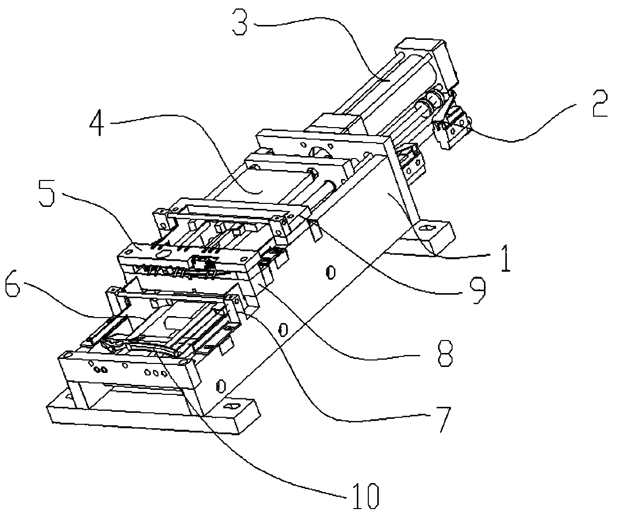
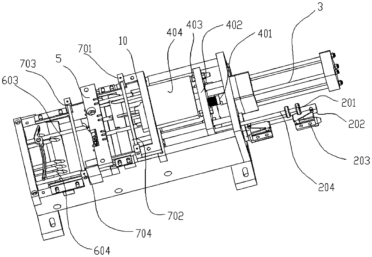
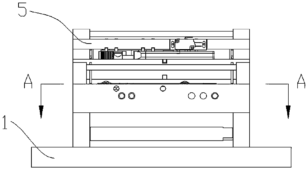
[0040] Such as Figure 1-Figure 10 Shown, the concrete structure of the present invention is:

[0041] An automatic feeding mechanism for pliers body processing, including a frame 1, a travel switch 2, a driving device 3, a pushing device 4, a processing trigger device 5, a guiding device 6, a height limiting device 7 and an auxiliary supporting device 8; The device 3 is fixed on the rear wall of the frame 1 and connected with the pusher device 4. An auxiliary support device 8 is fixed in the middle of the frame 1. The auxiliary support device 8 mainly provides support for the construction of other co...


PUM


Abstract

The invention discloses an automatic feeding mechanism for clamp body machining. The automatic feeding mechanism comprises a rack, a travel switch, a driving device, a pushing device, a machining triggering device, a guiding device, a height limiting device and an auxiliary supporting device; the driving device is fixed on the rear wall of the rack and connected with the pushing device, the auxiliary supporting device is fixed in the middle of the rack, the guiding device is erected on the auxiliary supporting device, and the pushing device and a clamp body to be machined are erected on the guiding device; the machining triggering device and the height limiting device are fixed on the upper surface of the rack; the pushing device comprises a first pushing plate and a second pushing plate,the height limiting device is arranged at the starting ends of the first pushing plate and the second pushing plate for pushing the clamp body to be machined, and the machining triggering device is arranged at the tail end of the first pushing plate for pushing the clamp body to be machined. The automatic feeding mechanism is used for clamp body machining, and can correctly identify the placementof the clamp body to be machined so as to trigger machining of a grinding disc.

Description

technical field [0001] The invention belongs to the technical field of hardware tool manufacturing, and relates to the correct screening of the placement position of pliers in the processing process, in particular to an automatic feeding mechanism for pliers body processing. Background technique [0002] Pliers are a hand tool used to clamp and fix workpieces or to twist, bend, and cut wires. The shape of the pliers is V-shaped, such as Figure 9 as well as Figure 10 As shown, the pliers are assembled from two identical pliers bodies, which respectively include a pliers head, a pliers handle and a grinding disc for assembly. [0003] The current processing of pliers generally processes the basic shape of the pliers first, and finally processes the grinding disc 1002 for assembly. Since the basic shape of the pliers has been determined, there is only one choice for the processing surface of the grinding disc. In the placement and transmission of the to-be-processed pliers...

Claims


Application Information

Patent Timeline
Patent Type & Authority Applications(China)
IPC IPC(8): B24B41/00B23Q7/00B65G47/24B65G47/82
CPCB23Q7/00B24B41/005B65G47/24B65G47/82
Inventor 王再德
Owner 湖南精专自动化技术有限公司
Why Eureka
Try Eureka