Electric automatization machining platform

A technology of electrical automation and processing platform, which is applied in the direction of workbench, manufacturing tools, workpiece clamping device, etc., which can solve the problems of inconvenient clamping and processing operations of products, and achieve the prevention of slider rotation, prevention of unstable fixation, and easy handling out effect

Inactive Publication Date: 2020-06-26
JIANGSU FOOD & PHARMA SCI COLLEGE
View PDF6 Cites 0 Cited by
  • Summary
  • Abstract
  • Description
  • Claims
  • Application Information

AI Technical Summary

Problems solved by technology

[0003] At present, most of the existing electrical automation processing platforms on the market have the following deficiencies: the product is inconvenient to clamp and it is inconvenient to perform processing operations, and the existing electrical automation processing platforms are not easy to solve such problems. Therefore, there is an urgent need for an electrical automation processing platform to solve above question

Method used


Image

  • Electric automatization machining platform
  • Electric automatization machining platform
  • Electric automatization machining platform

Examples


Embodiment 1

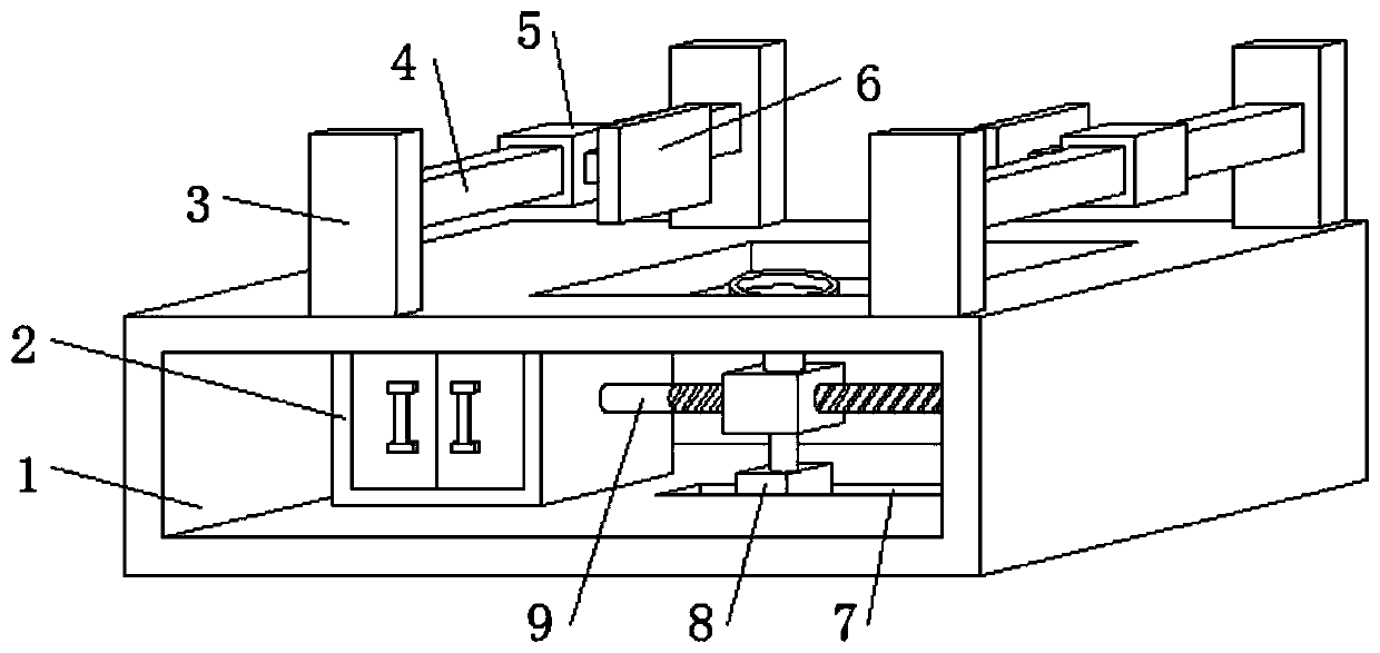
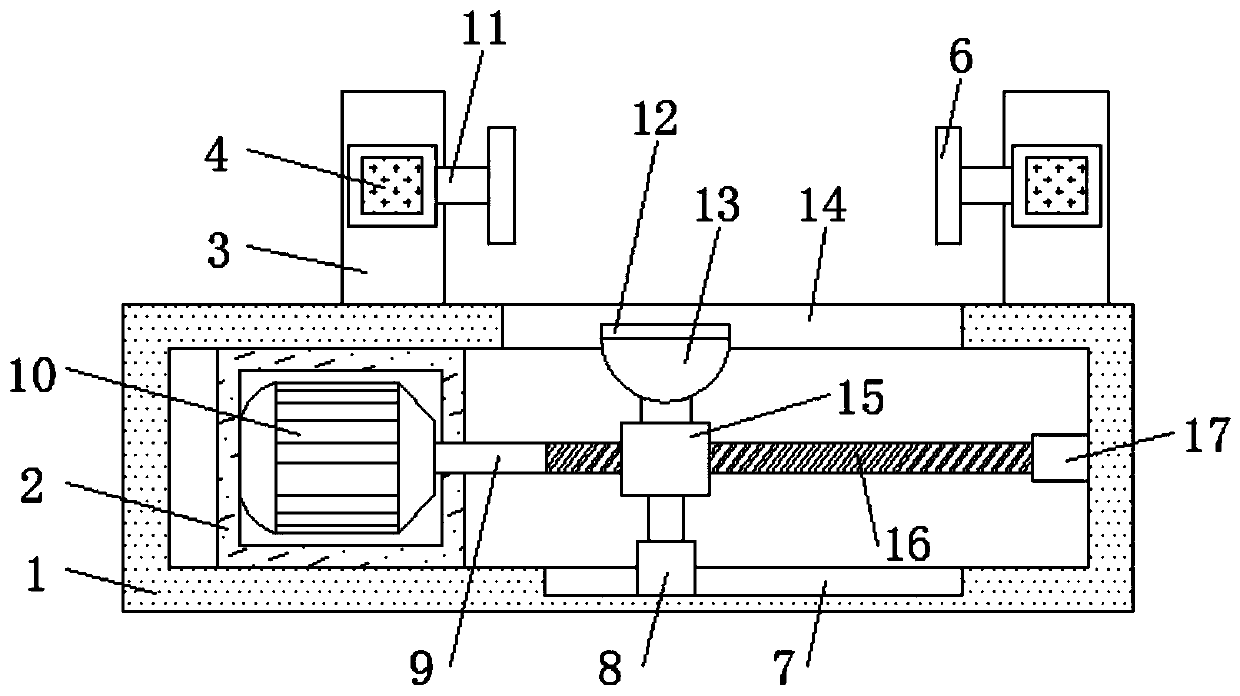
[0024] refer to Figure 1-2 , an electrical automation processing platform, comprising a rectangular frame 1, a motor box 2 is fixed on one side of the bottom inner wall of the rectangular frame 1 by bolts, a motor 10 is fixed on one side of the inner wall of the motor box 2 by bolts, and one end of the output shaft of the motor 10 The key is connected with a transmission shaft 9, and one end of the transmission shaft 9 is located outside the motor box 2, and one end of the transmission shaft 9 is keyed with a screw rod 16, and the inner wall of the side of the rectangular frame 1 away from the motor box 2 is fixed with a bearing 17, and the screw rod One end of 16 is rotatably inserted on the circumferential inner wall of bearing 17, and the circumferential outer wall of screw rod 16 is slidably connected with slide block 15, and the top outer wall of slide block 15 is fixed with electromagnetic chuck 13 by bolts.

[0025] In the present invention, the magnetically conductive...

Embodiment 2

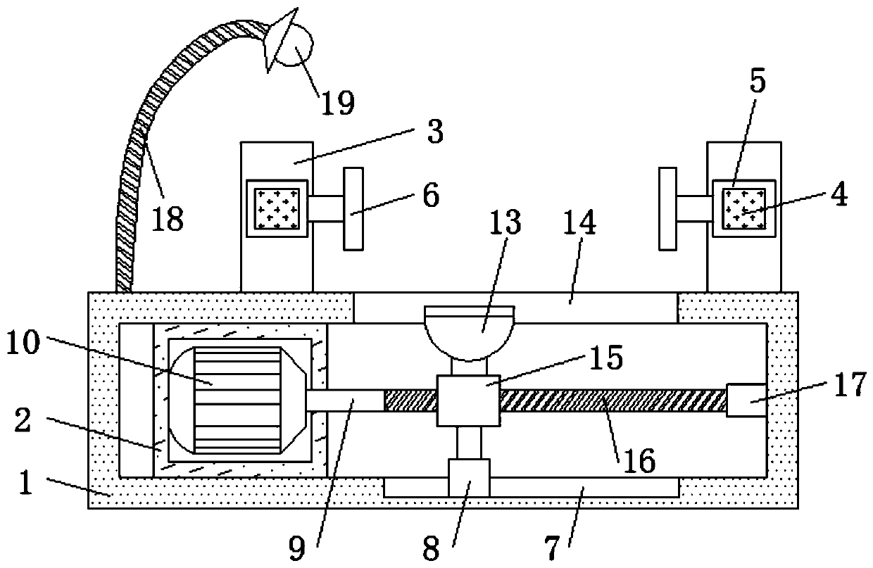
[0028] refer to image 3 , an electrical automation processing platform. Compared with Embodiment 1, this embodiment also includes a plastic elbow 18 and a lighting lamp 19. The plastic elbow 18 is fixed on one side of the outer wall of the top of the rectangular frame 1 by bolts, and 19 sets of lighting lamps Connected to one end of the plastic elbow 18.

[0029] During use, one side of the top of the rectangular frame 1 is provided with an illuminating lamp 19, which can provide illumination, and the plastic elbow 18 can be bent and stretched to change its position, so as to provide illumination to the dead corner of the workpiece conveniently.


PUM


Abstract

The invention discloses an electric automatization machining platform. Aiming at the problems that a product cannot be conveniently clamped, and the machining operation cannot be conveniently carriedout, the following scheme is provided. According to the scheme, the platform comprises a rectangular frame, a motor box is fixed to one side of the inner wall of the bottom of the rectangular frame through a bolt, a motor is fixed to the inner wall of one side of the motor box through a bolt, one end of an output shaft of the motor is in key connection with a transmission shaft, one end of the transmission shaft is located outside the motor box, one end of the transmission shaft is in key connection with a screw rod, a bearing is fixed to the inner wall of the side, away from the motor box, ofthe rectangular frame through a bolt, one end of the screw rod is inserted in the circumferential inner wall of the bearing in a rotating mode, and the circumferential outer wall of the screw rod isin sliding connection with a sliding block. According to the platform, a coil in an electromagnetic chuck is powered on to generate magnetic force, and the magnetic force passes through a magnetic conductive panel to tightly attract a workpiece in contact with the surface of the magnetic conductive panel, so that the workpiece is fixed; the coil is demagnetized after being powered off, so that theworkpiece is not adsorbed any more, and the workpiece is conveniently taken out; and therefore, the workpiece can be conveniently fixed and taken down.

Description

technical field [0001] The invention relates to the technical field of processing platforms, in particular to an electric automatic processing platform. Background technique [0002] Electrical engineering and automation is a new discipline in the field of electrical information, but because it is closely related to people's daily life and industrial production, it develops very rapidly and has become a high-tech industry widely used in industry, agriculture, national defense and other fields. Automation usually requires the processing of products, so an electrical automation processing platform is required. [0003] At present, most of the existing electrical automation processing platforms on the market have the following deficiencies: the product is inconvenient to clamp and it is inconvenient to perform processing operations, and the existing electrical automation processing platforms are not easy to solve such problems. Therefore, there is an urgent need for an electric...

Claims


Application Information

Patent Timeline
Patent Type & Authority Applications(China)
IPC IPC(8): B25H1/10B25B11/00F21V33/00
CPCB25H1/10B25B11/002F21V33/00
Inventor 唐媛红花勇
Owner JIANGSU FOOD & PHARMA SCI COLLEGE
Why Eureka
Try Eureka