A kind of auv modular carrier structure
A modular and carrier-based technology, applied in transportation and packaging, ships, underwater operating equipment, etc., can solve the problems of restricting AUVs to perform different tasks, is not conducive to the diversity of AUV functions, and cannot flexibly configure functional modules, etc., to achieve a compact structure , Simple structure, flexible and convenient to use
- Summary
- Abstract
- Description
- Claims
- Application Information
AI Technical Summary
Problems solved by technology
Method used
Image
Examples
Embodiment 1
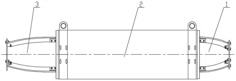
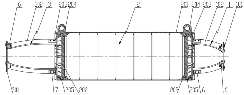
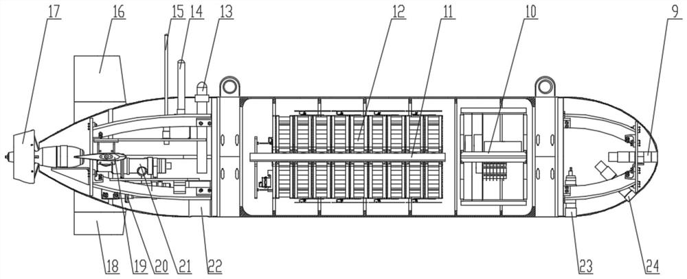
[0085] combine figure 1 , figure 2 and image 3 , this embodiment mainly includes a bow section carrier 1, an energy section carrier 2, a stern section carrier 3, and a horn-shaped connector 6, and the specific order is the bow section carrier 1, the energy section carrier 2, and the stern section carrier 3.
[0086] The connection between each cabin section adopts a unified connection structure. The bow section carrier 1 and the energy section carrier 2 are connected by a horn-shaped connector 6 bolts, and the energy section carrier 2 and the stern section carrier 3 are connected by a second horn-shaped connector. Connector 7 is bolted.
[0087] The specific implementation of the AUV modular carrier structure in the first embodiment is as follows:
[0088] combine Figure 10 , The bow section carrier 1 is composed of a bow section end flange 101 , a bow section support rod 102 and a horn-shaped connector 6 .
[0089] Install through holes at the ends of the 45-degree ce...
Embodiment 2
[0108] The specific implementation of the AUV modular carrier structure in the second embodiment is as follows:
[0109] combine Figure 12 and Figure 16 , on the basis of the AUV modular carrier structure in the first embodiment, the No. 1 expansion carrier 4 is installed between the bow segment carrier 1 and the energy segment carrier 2 .
[0110] The No. 1 expansion carrier 4 is composed of the No. 1 expansion compartment support rod 401 , the compartment connection flange 8 and a horn-shaped connector 6 .
[0111] Install through holes at the ends of the 45-degree centerline and 135-degree centerline of the cabin connecting flange 8 flange surface, and install through holes at one end of the support rod 401 of the No. 1 expansion cabin section. Mounting through holes are arranged on the two mounting surfaces. There are four support rods 401 in the No. 1 expansion cabin, arranged in an X shape. Each support rod 401 in the No. 1 expansion cabin is vertically connected to...
Embodiment 3
[0118] The specific implementation of the AUV modular carrier structure in the third embodiment is as follows:
[0119] combine Figure 5 and Figure 15 , on the basis of the AUV modular carrier structure in Embodiment 2, between the bow segment carrier 1 and the No. 1 extension carrier 4, the No. 2 extension carrier 5 is installed, and between the energy segment carrier 2 and the stern segment carrier 3, Install the second extension carrier 5.
[0120] The No. 2 expansion carrier 5 is composed of the No. 2 expansion compartment support bar 501 , the compartment connection flange 8 and a horn-shaped connector 6 . Install through holes at the ends of the 45-degree centerline and 135-degree centerline of the flange surface of the cabin connecting flange 8, and install through holes at one end of the support rod 501 of the No. Mounting through holes are arranged on the two mounting surfaces. There are four supporting rods 501 in the No. 2 extended cabin, arranged in an X shap...
PUM
 Abstract
Description
Claims
Application Information
 - R&D
- Intellectual Property
- Life Sciences
- Materials
- Tech Scout
- Unparalleled Data Quality
- Higher Quality Content
- 60% Fewer Hallucinations
Browse by: Latest US Patents, China's latest patents, Technical Efficacy Thesaurus, Application Domain, Technology Topic, Popular Technical Reports.
© 2025 PatSnap. All rights reserved.Legal|Privacy policy|Modern Slavery Act Transparency Statement|Sitemap|About US| Contact US: help@patsnap.com


