

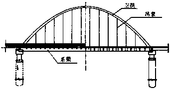
Self-anchored cable-stayed tied arch bridge
A tie-bar arch bridge, self-anchored technology, applied to bridges, bridge parts, bridge construction, etc., can solve problems such as structural collapse
- Summary
- Abstract
- Description
- Claims
- Application Information
AI Technical Summary
Problems solved by technology
Method used
Image

Examples
Embodiment 1
[0115] Embodiment 1: as Figure 11 As shown, it is a self-anchored cable-stayed arch bridge with variable cross-section continuous beams, according to Figure 13 The steps of construction are as follows:
[0116] The first step is to complete pier 8, pier 9, pier 8' and pier 9' according to conventional construction methods;
[0117] The second step is to install support 7 on the pier caps of pier 8, pier 8', pier 9, and pier 9' respectively, and formwork-in-place to complete the beam body block of block 0 and block 0' of the main span tie bar ;
[0118] The third step is to use the hanging basket cantilever cast-in-place method or the hanging basket cantilever assembly method to carry out the No. 1 block and No. 1' block, No. 2 block and No. 2' block of the main span tie bar 1 and side span continuous beam 2 in sequence. block ... and other beam body blocks, until the closing sections 11, 11' of the side-span continuous beam 2 and the closing section 10 of the main span ti...
Embodiment 2
[0124] Embodiment 2: as Figure 12 As shown, it is a self-anchored cable-stayed arch bridge with constant cross-section continuous beams, according to Figure 14 The steps of construction are as follows:
[0125] The first step is to complete pier 8, pier 9, pier 8' and pier 9' according to conventional construction methods;
[0126] In the second step, the construction method of the full hall support is used to complete the temporary project of the construction support of the cast-in-place beam body of the main span tie rod 1 and the side span continuous beam 2 ( Figure 14 not marked in);
[0127] The third step is to cast in-situ the main span tie bar 1 and the side span main beam 2 section by section on the full hall support until the side span closure and middle span closure of the entire continuous beam are completed successively;
[0128] The fourth step is to cantilever or cantilever arch rib segments on the main beams of the main span and side spans; some temporary...
Embodiment 3
[0133] Embodiment 3: as Figure 12 As shown, it is a self-anchored cable-stayed arch bridge with constant cross-section continuous beams, according to Figure 15 The steps of construction are as follows:
[0134] The first step is to complete pier 8, pier 9, pier 8' and pier 9' according to conventional construction methods;
[0135] In the second step, the beam blocks 0 and 0' at the top of the main pier, the beam blocks 1 and 1' of the main span and the main beam of side span 2 are completed by using the full hall support method;
[0136] The third step is to complete the cantilevered or cantilevered construction of all the beams of the main span except the closing section, and simultaneously carry out the cantilevered or cantilevered construction of the arch rib 3; some temporary auxiliary cables can also be added according to the construction needs;
[0137] The fourth step is to complete the construction of the closing section of the main girder 1 of the main span tie b...
PUM
 Abstract
Description
Claims
Application Information