Wall face coating spraying equipment for building decoration

A technology for spraying equipment and coatings, applied in the direction of construction and building structure, can solve the problems of difficult continuous spraying, poor practicability, and pulling up the inner box, so as to achieve full and fast stirring, good stirring effect and good spraying effect. Effect

Active Publication Date: 2020-06-26
浙江纳川纸业有限公司
View PDF9 Cites 4 Cited by
  • Summary
  • Abstract
  • Description
  • Claims
  • Application Information

AI Technical Summary

Problems solved by technology

But when the paint in the inner box is loaded too much, it is difficult to pull up the inner box by manpower. If the paint load is small, it is difficult to carry out continuous spraying for a long time, and the practicability is not strong.

Method used


Image

  • Wall face coating spraying equipment for building decoration
  • Wall face coating spraying equipment for building decoration
  • Wall face coating spraying equipment for building decoration

Examples


Embodiment 1

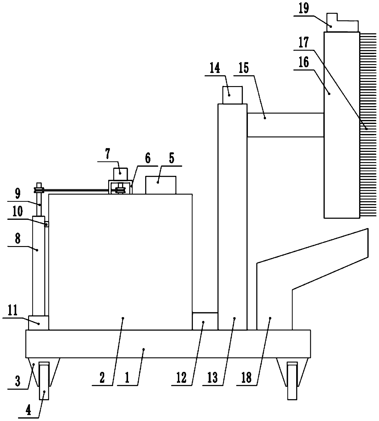
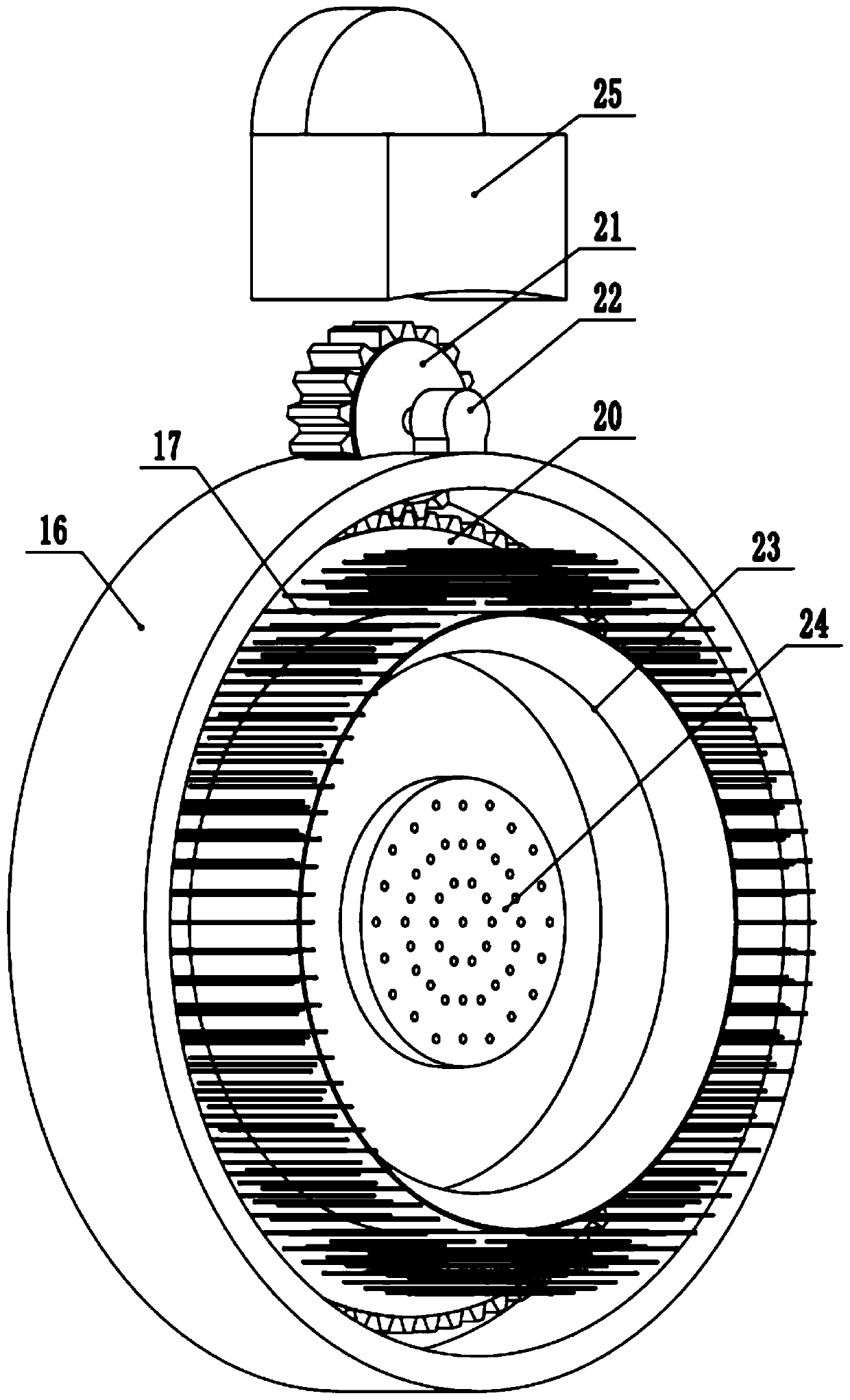
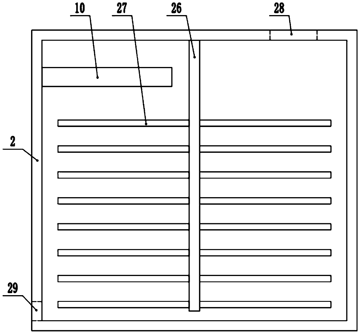
[0025] see Figure 1-4 , a wall paint spraying equipment for architectural decoration, comprising a base 1, the four corners of the bottom of the base 1 are fixedly connected to a wheel base 3, the wheel base 3 is rotatably connected to a walking wheel 4, and the top of the base 1 is fixedly provided with a mixing box 2, One end of the top of the mixing box 2 is fixedly connected to the feed hopper 5, and one side of the mixing box 2 is provided with a lifting device 13, and the delivery pump 12 is fixedly connected between the lifting device 13 and the mixing box 2. The column 15 is fixedly connected to the outer baffle 16, and the outer baffle 16 is provided with a dust removal device and a spraying device, the inside of the mixing box 2 is provided with a stirring mechanism, and the outside of the mixing box 2 is provided with an external circulation mixing mechanism.

[0026] Described stirring mechanism comprises the motor frame 6 that is fixedly arranged on the top of mi...

Embodiment 2

[0034] see Figure 1-4 , the other content of this embodiment is the same as that of Embodiment 1, except that the outer circulation mixing mechanism includes a return bottom cover 11 fixedly arranged on the bottom of the outer side of the mixing box 2, and the top end of the return bottom cover 11 is fixedly connected to lift The pipe 8, the top side of the riser 8 and the mixing tank 2 are fixedly connected to the return pipe 10, the riser 8 is coaxially provided with a lift shaft 9, and the outer side of the lift shaft 9 is fixedly connected to the spiral lift plate, and the lift shaft 9 is connected to the mixing tank. Motor 7 transmission is connected.

[0035] The top and bottom sides of the mixing box 2 are respectively provided with a feed inlet 28 and a feed inlet 29 corresponding to the feed hopper 5 and the return bottom cover 11 .

[0036] The present invention can realize the cyclic stirring of the paint by setting the stirring mechanism and the external circulat...


PUM


Abstract

The invention discloses wall face coating spraying equipment for building decoration, and relates to the field of building decoration. A base is included. The top of the base is fixedly provided witha mixing box. An elevating device is arranged on one side of the mixing box. A conveying pump is fixedly connected between the elevating device and the mixing box. The elevating device is connected with a connecting column. The connecting column is fixedly connected with an outer stop cover. A dust removal device and a spraying device are arranged in the outer stop cover. A stirring mechanism is arranged in the mixing box. An outer circulating mixing mechanism is arranged at the outer portion of the mixing box. Through the arrangement of the stirring mechanism and the outer circulating mixingmechanism, coating circulating type stirring can be achieved, coating stirring is sufficient and rapid, and the stirring effect is good; through the arrangement of the dust removal device, brushing type dust removal can be conducted on the wall face before spraying, dust on the wall face is removed, a coating can be well combined with the wall face during later spraying; and through the arrangement of the spraying device, uniform spraying can be conducted on the wall face, and the wall face spraying effect is good.

Description

technical field [0001] The invention relates to the field of architectural decoration, in particular to a wall paint spraying equipment for architectural decoration. Background technique [0002] In the current home decoration, many families still use artificial paint, which is not only inefficient, but also causes the problem of wasting paint during the process of painting; there are paint sprayers on the market, but their structure is simple. The paint mixing tank is connected to the pump body, and the internal materials are pumped out and sprayed on the wall. However, due to the internal structure, the paint enters the conveying pipeline at the beginning, and cannot be fully stirred. As a result, the paint raw materials in the pipeline need to be removed before the spraying starts. release, resulting in loss of raw materials and waste of paint. [0003] In the Chinese invention patent document with the notification number CN108086648B, a kind of wall paint spraying equip...

Claims


Application Information

Patent Timeline
Patent Type & Authority Applications(China)
IPC IPC(8): E04F21/08E04F21/00
CPCE04F21/00E04F21/08
Inventor 郑为香
Owner 浙江纳川纸业有限公司
Why Eureka
Try Eureka