A petroleum and petrochemical valve with a locking structure

A locking structure and valve technology, applied to valve details, valve devices, sliding valves, etc., can solve problems such as inability to realize fast opening and closing of valves

Active Publication Date: 2020-10-23
JIANGSU JIANGYUAN MASCH CO LTD
View PDF1 Cites 0 Cited by
  • Summary
  • Abstract
  • Description
  • Claims
  • Application Information

AI Technical Summary

Problems solved by technology

However, this device cannot realize the rapid opening and rapid closing of the valve.

Method used


Image

  • A petroleum and petrochemical valve with a locking structure
  • A petroleum and petrochemical valve with a locking structure
  • A petroleum and petrochemical valve with a locking structure

Examples


specific Embodiment approach 1

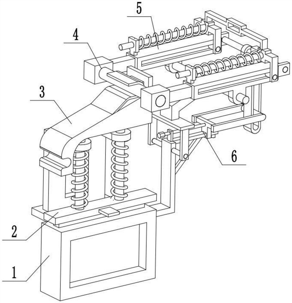
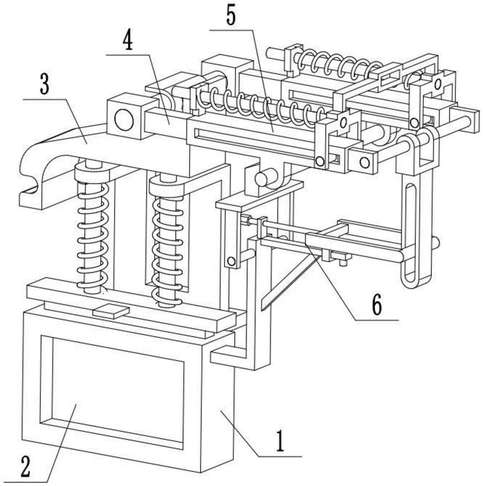
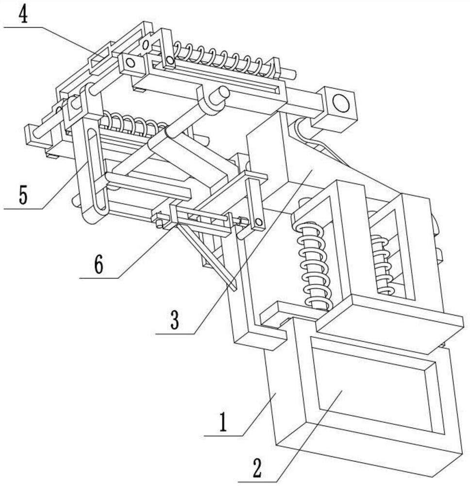
[0028] Combine below Figure 1-10 Describe this embodiment, a petroleum and petrochemical valve with a locking structure, including a valve housing 1, a valve plate 2, a locking piece 3, a locking piece 4, a locking piece sliding seat 5, and a locking adjustment mechanism 6. The valve plate 2 described above is slidably connected in the valve housing 1, the locking piece 3 is arranged on the upper end of the valve plate 2, the locking piece 4 is connected with the locking piece 3, and the locking piece 4 is movably connected to the locking piece sliding On the seat 5 , the locking member sliding seat 5 is arranged on the locking adjusting mechanism 6 , the locking adjusting mechanism 6 is connected with the locking member sliding seat 5 , and the locking adjusting mechanism 6 is arranged on the valve housing 1 . When in use, the valve housing 1 is in a closed state under normal conditions, and the clamping part 4 is clamped on the right end of the locking part 3, and the clamp...

specific Embodiment approach 2

[0030] Combine below Figure 1-10To illustrate this embodiment, the valve plate 2 is sealed and slidably connected in the valve housing 1, the valve housing 1 is provided with a fixing frame 1-1, and the upper end of the valve plate 2 is fixedly connected to two spring sleeves Rod 2-1, the two spring sleeve rods 2-1 are all slidingly fitted and connected to the fixed frame 1-1, and a compression spring 2-2 is respectively sleeved on the two spring sleeve rods 2-1; the compression spring 2- The two ends of 2 are respectively fixedly connected to the fixed frame 1-1 and the valve plate 2; the upper end of the valve plate 2 is fixedly connected to the dial 2-3; the locking member 3 is arranged on the two spring sleeve rods 2-1. When the plate 2-3 is pulled upward, it drives the valve plate 2 to move upward, and the valve plate 2 opens the valve housing 1 to realize rapid opening. At the same time, the two compression springs 2-2 are compressed to store force. When the valve plat...

specific Embodiment approach 3

[0032] Combine below Figure 1-10 To illustrate this embodiment, the top surface of the locking member 3 is inclined upward from left to right to form a right-angled triangle structure, and the locking member 3 is fixedly connected to the upper ends of the two spring sleeve rods 2-1; the locking member 4 It is clamped on the right end of the locking piece 3.

[0033] The left end of the locking member 3 is provided with a downward extension, and the extension is provided with a locking groove 3-1, and the right end of the locking member 3 is fixedly connected to the connecting plate 3-2, and the U-shaped locking seat 3-3 is fixedly connected to the connection plate 3-2, and the transition slant plate 3-4 is fixedly connected to the lower end of the U-shaped card seat 3-3 and the slope of the locking piece 3; the transition slant plate 3-4 is connected to the U-shaped The joint of the card position seat 3-3 is a transitional arc surface; the card position member 4 is clamped i...


PUM


Abstract

The invention provides a petroleum and petrochemical valve with a locking structure, and relates to the technical field of valves. The petroleum and petrochemical valve comprises a valve shell, a valve plate, a locking piece, a clamping piece, a locking piece slide and a locking adjusting mechanism. The beneficial technical effect is that rapid opening and closing of the valve can be realized, andopening and closing states can be automatically locked. The valve plate is slidably connected in the valve shell; the locking piece is arranged at the upper end of the valve plate; the clamping pieceis connected with the locking piece in a matched way; the clamping piece is movably connected to the locking piece slide; the locking piece slide is arranged on the locking adjusting mechanism; the locking adjusting mechanism is connected with the locking piece slide in a matched way; and the locking adjusting mechanism is arranged on the valve shell.

Description

technical field [0001] The invention relates to the technical field of valves, in particular to a petroleum and petrochemical valve with a locking structure. Background technique [0002] The patent number is CN201920377719.5 for a valve with a locking device. This utility model relates to the technical field of valves and discloses a valve with a locking device, including a valve body whose top is fixedly connected with a fixed pipe. The top of the fixed pipe is fixedly connected with a fixed nut, the top of the fixed nut is threadedly connected with a screw rod, the top of the screw rod is fixedly connected with a valve stem, and the bottom of the screw rod is fixedly connected with a fixed rod. For the valve with locking device, fixed blocks are fixed on both sides of the fixed pipe, and a compression spring is connected inside the fixed block. When the position rod is moved down, the valve stem can be rotated to control the opening and closing of the valve, the connecti...

Claims


Application Information

Patent Timeline
Patent Type & Authority Patents(China)
IPC IPC(8): F16K3/02F16K3/30F16K35/00
CPCF16K3/0281F16K3/30F16K35/00
Inventor 韩文豪韩正海匡茜茜
Owner JIANGSU JIANGYUAN MASCH CO LTD
Why Eureka
Try Eureka