LED fluorescent lamp

A technology for LED fluorescent lamps and lamp tubes, which is applied in the direction of light source, electric light source, light source fixing, etc. It can solve the problems of the stability of LED fluorescent lamps, the inability of lamp tubes to provide sufficient fixing force, and the influence of installation, disassembly and lighting range of LED fluorescent lamps, etc. , to achieve the effect of enhancing the use effect and ensuring the use effect

Inactive Publication Date: 2020-06-26
安徽瑞雪照明股份有限公司
View PDF0 Cites 0 Cited by
  • Summary
  • Abstract
  • Description
  • Claims
  • Application Information

AI Technical Summary

Problems solved by technology

[0004] In order to make up for the deficiencies in the prior art, solve the problem that although LED fluorescent lamps are widely used in daily life, the stability of LED fluorescent lamps in use will often be affected; when a housing is provided to fix the LED fluorescent lamp, it will affect the LED. For the installation, disassembly and lighting range of fluorescent lamps, when only the lamp tube is inserted into the lamp holder, the lamp holder in the prior art cannot provide sufficient fixing force for the lamp tube; the present invention proposes a LED fluorescent lamp

Method used


Image

  • LED fluorescent lamp
  • LED fluorescent lamp
  • LED fluorescent lamp

Examples


Embodiment approach

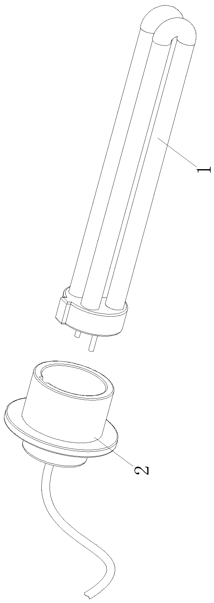
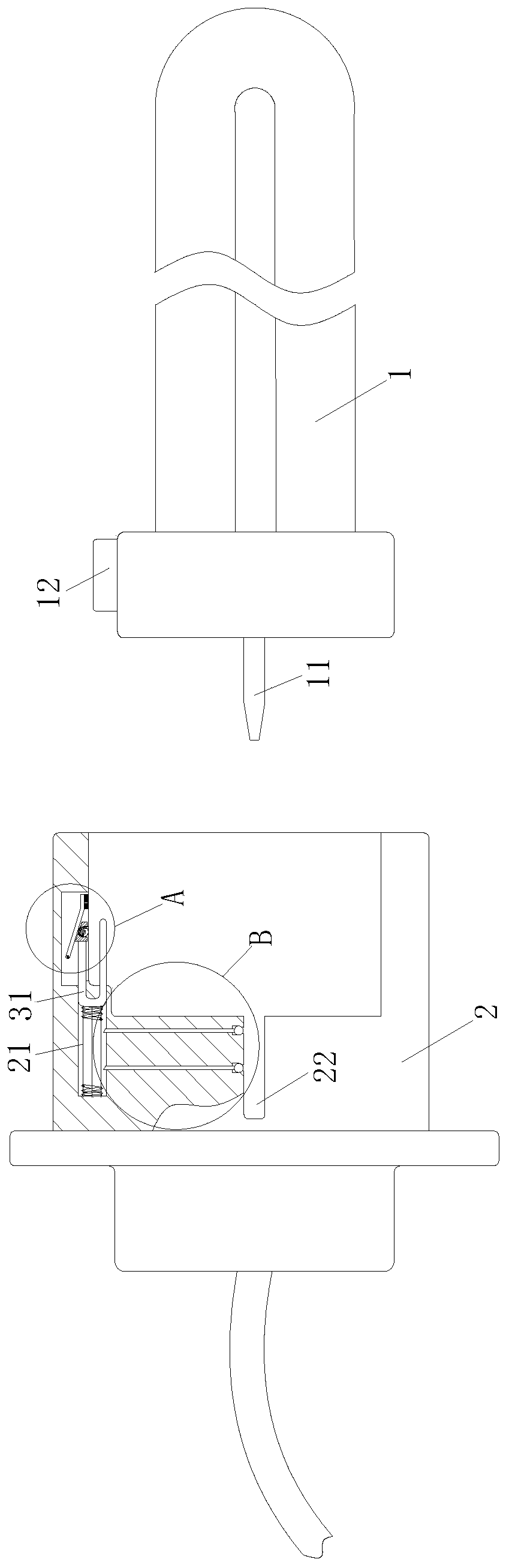
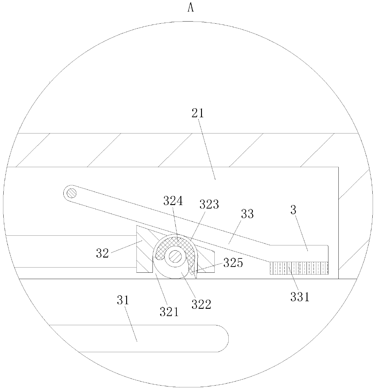
[0022]As an embodiment of the present invention, the trapezoidal block 32 is provided with a cavity 321; the cavity 321 is slidably connected with a roller 322, and when the lamp tube 1 is inserted into the lamp holder 2, the roller 322 is connected with the hinge rod respectively. The side wall of 33 is in contact with the side wall of the lamp tube 1, and the sliding of the trapezoidal block 32 is converted into rolling by the roller 322, which reduces the resistance of the trapezoidal block 32; during work, when people need to install an LED fluorescent lamp, first insert the lamp tube 1 In the lamp holder 2, during the insertion process of the lamp tube 1, the lamp tube 1 will generate a thrust to the U-shaped rod 31, and the U-shaped rod 31 will slide in the chute 21 after being pushed, and the U-shaped rod 31 will slide during the sliding process. Drive the trapezoidal block 32 to slide, so that the hinge rod 33 rotates under the torsion force of the torsion spring, and p...


PUM


Abstract

The invention belongs to the technical field of home lighting, and particularly relates to an LED fluorescent lamp. The lamp comprises a lamp tube and a lamp holder, the lamp tube is installed in thelamp holder, and a power connection column is arranged at the end of the lamp tube. Chutes are formed in the side wall of the lamp holder, and power connection grooves are formed in the position closeto the power connection column. Clamping units are arranged in the chutes. Each clamping unit comprises a U-shaped rod, a trapezoidal block and a hinge rod; the trapezoidal blocks are installed at the end, located in the chutes, of the U-shaped rods. The hinge rods are hinged to the side walls of the chutes through a torsional spring, the side walls of the hinge rods make contact with the side walls of the trapezoidal blocks all the time, and friction blocks are arranged at the ends of the hinge rods. According to the LED fluorescent lamp, the fixing effect on the lamp tube is enhanced through cooperation of the lamp tube, the lamp holder and the clamping units, the lamp tube can be fixed to the lamp holder except for the supporting force of the shell on the lamp tube, it is guaranteed that electrification between the lamp tube and the lamp holder is stable, and the using effect of the LED fluorescent lamp is enhanced.

Description

technical field [0001] The invention belongs to the technical field of home lighting, in particular to an LED fluorescent lamp. Background technique [0002] LED fluorescent lamps, commonly known as straight tube lamps, are a substitute for traditional fluorescent tubes, which are reflected in two aspects of energy saving and environmental protection. The size and installation method are the same as traditional fluorescent lamps, but the light emitting principle is to use LED semiconductor chips to emit light. LED fluorescent lamps have many advantages: high color rendering, color rendering index CRI=80, can truly reproduce the original bright colors of objects, and create a comfortable light environment ;Long life, the lamp tube is made of glass tube material with good thermal conductivity, equipped with a special aluminum alloy radiator with high thermal conductivity to ensure that the junction temperature of the LED is always lower than 80°C, the light decay is less than ...

Claims


Application Information

Patent Timeline
Patent Type & Authority Applications(China)
IPC IPC(8): F21S8/00F21V21/02F21V19/00F21V23/06F21V17/10F21Y115/10
CPCF21S8/00F21V17/10F21V19/001F21V21/02F21V23/06F21Y2115/10
Inventor 王爱强张勤伟刘亚宝
Owner 安徽瑞雪照明股份有限公司
Why Eureka
Try Eureka